Respirator having valve with an ablated flap

a technology of ablating flaps and respirators, which is applied in the field of respirator valves with ablating flaps, can solve the problems of increasing the chance that the wearer will remove the mask, affecting the performance of the respirator, and causing discomfort at the same time, so as to improve the valve performance, and reduce the risk of infection

Inactive Publication Date: 2012-07-05
3M INNOVATIVE PROPERTIES CO
View PDF2 Cites 29 Cited by
  • Summary
  • Abstract
  • Description
  • Claims
  • Application Information

AI Technical Summary

Benefits of technology

[0012]The provision of an ablated flap is beneficial in that the flap can be tailored to have characteristics in stiffness and thickness at specifically desired areas on the flap, which specifically tailored areas can enable the flap to open with minimal force or can alter a particular valve attribute in a desired manner. A valve that can open continuously under minimal force, with little pressure drop across the valve, requires less energy to operate. Since the wearer is the power source for operating the valve, the wearer does not need to work as hard when wearing a respirator where the valve exhibits optimal performance. Improved valve performance, in turn, can make respirators more comfortable to wear over extended time periods, which is particularly beneficial from a safety standpoint, since wearers are less likely to remove the mask from their face in contaminated environments.
[0013]The present invention also may be beneficial from a manufacturing standpoint since individual flaps can be tailored during product manufacture to satisfy specific quality control / performance requirements. By ablating certain flap portions during valve assembly, less products may be rejected for failing to meet desired performance requirements during the quality control assessment.

Problems solved by technology

When wearing a respirator in a contaminated environment, wearers are comforted with the knowledge that their health is being protected, but they are, however, contemporaneously discomforted by the warm, moist, exhaled air that accumulates around their face.
The greater this facial discomfort is, the greater chances are that the wearer will remove the mask from their face to alleviate the unpleasant condition.

Method used


Image

  • Respirator having valve with an ablated flap
  • Respirator having valve with an ablated flap
  • Respirator having valve with an ablated flap

Examples


example 1

[0078]Example 1 represents an example of a valve having an ablated flap of the present invention. The flap of the example valve was formed from an extruded sheet of 0.46 mm thick polyisoprene rubber, available from Fulflex, Inc., Brattleboro, Vt. The rubber sheet was cut into a flap in the shape shown in FIGS. 7b. The flap 44 was 17.6 mm at the narrow end 46, and 22.4 mm at the wide end 48. Length of the flap from wide to narrow end was 25 mm. The flap had two 2 mm diameter anchoring holes 59 placed on the narrow end of the flap to facilitate attachment to the flow test fixture. The holes 59 were centered 2 mm from the narrow end and sides of the flap as illustrated. An ablated hinge zone 58 was formed at the narrow end 46 of the flap. The hinge zone 58 began at the narrow end of the flap and extended 5.5 mm towards the wide end of the flap. Width of the hinge zone was 10 mm and centered from side to side on the flap. The hinge zone 58 was formed using a laser to ablate evenly space...

example 2

[0080]Example 2 was formed and tested as Example 1 with the exception that the laser was operated at a 12% power.


PUM

PropertyMeasurementUnit
lengthaaaaaaaaaa
diameteraaaaaaaaaa
diameteraaaaaaaaaa

Abstract

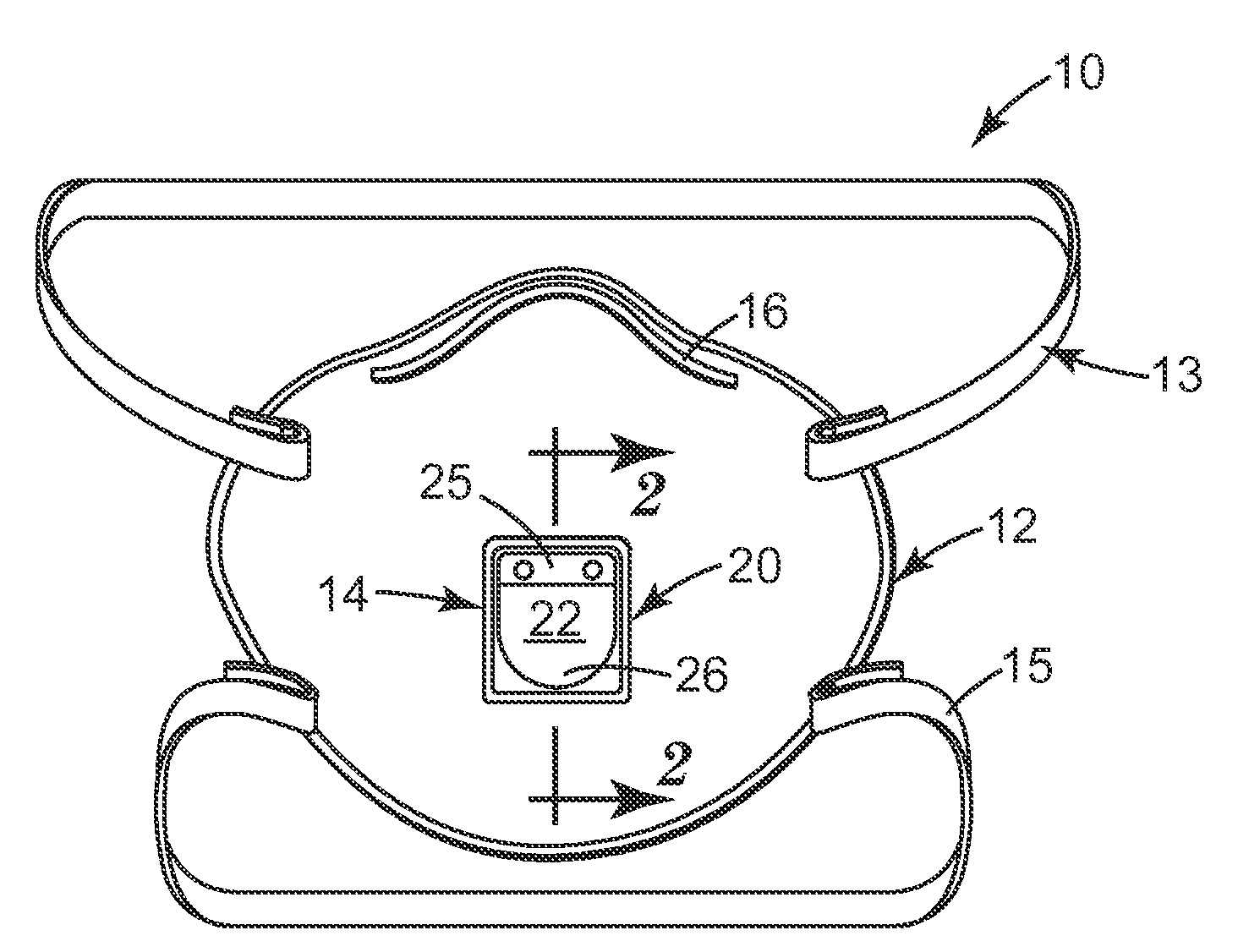
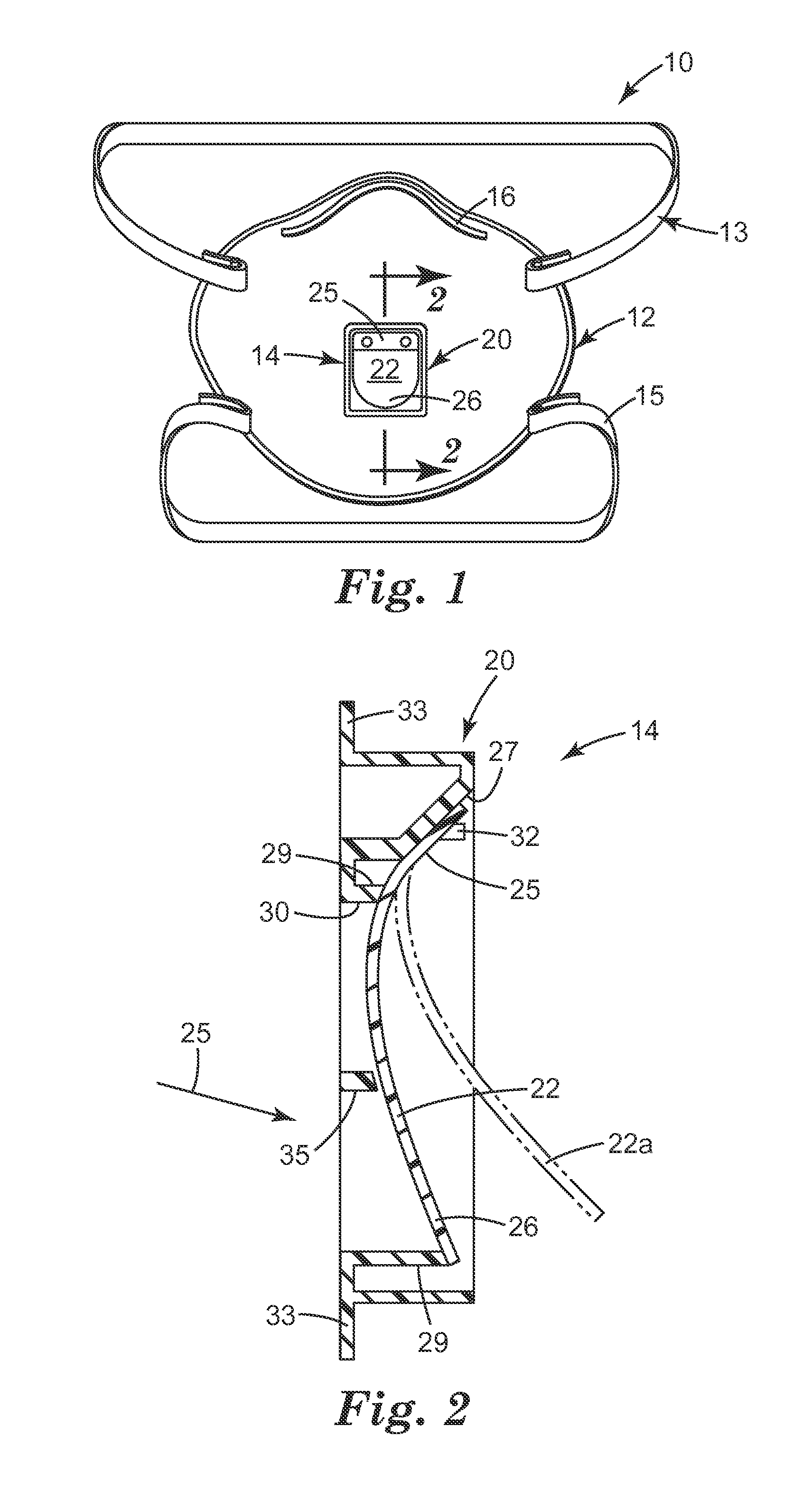
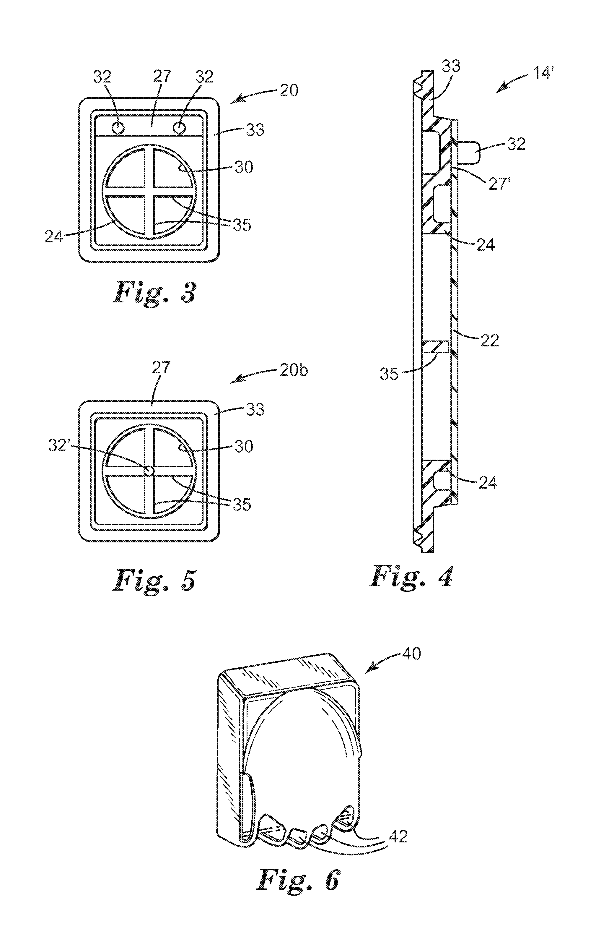
A respirator 10 that has a mask body 12, a harness 13, and an exhalation valve 14. Both the harness 13 and the exhalation valve 14 are secured to the mask body 12. The exhalation valve 14 comprises a valve seat 20 and a flap 22 that has a surface 57 that has been ablated. Through use of an ablated flap, the flap characteristics can be better fashioned to achieve desired valve performance. The valve flap can be fashioned to remain closed under any orientation but also to open with minimal force or pressure from the wearer's exhaled air. A valve having these qualities provides a respirator that is more comfortable for a person to wear, which can be particularly beneficial to workers who wear respirators for extended time periods.

Description

CROSS REFERENCE TO RELATED APPLICATION[0001]This application claims the benefit of U.S. Provisional Patent Application Ser. No. 61 / 427,882, filed Dec. 29, 2010.[0002]The present invention pertains to a respirator having an exhalation valve that uses a flap that has one or more ablated areas.BACKGROUND[0003]Persons who work in polluted environments commonly wear respirators to protect themselves from inhaling airborne contaminants. Respirators typically have a fibrous or sorbent filter that is capable of removing particulate and / or gaseous contaminants from the air. When wearing a respirator in a contaminated environment, wearers are comforted with the knowledge that their health is being protected, but they are, however, contemporaneously discomforted by the warm, moist, exhaled air that accumulates around their face. The greater this facial discomfort is, the greater chances are that the wearer will remove the mask from their face to alleviate the unpleasant condition.[0004]To redu...

Claims


Application Information

Patent Timeline
Patent Type & Authority Applications(United States)
IPC IPC(8): A62B18/10A62B27/00B23P17/00
CPCA62B18/025Y10T29/49826Y10T29/49764A62B18/10A61M16/06
Inventor INSLEY, THOMAS I.XUE, THOMAS J.
Owner 3M INNOVATIVE PROPERTIES CO
Why Eureka
Try Eureka