Method and apparatus for injecting a chemical into a process upstream of an inline mixer

a technology of inline mixer and process flow media, which is applied in the direction of mixing, rotary stirring mixer, transportation and packaging, etc., can solve the problems of not introducing the chemical, not accepting less than the desired mixing performance, adding additional chemicals, etc., and achieves the optimal mixing performance, small pressure drop, and sufficient width

Inactive Publication Date: 2004-01-22
ITT MFG ENTERPRISES LLC
View PDF16 Cites 29 Cited by
  • Summary
  • Abstract
  • Description
  • Claims
  • Application Information

AI Technical Summary

Benefits of technology

0010] In effect, this present invention uses a new and unique slotted injection pipe that traverses a process pipe and introduces the chemical at the optimal location for performance of the downstream dynamic mixer. The optimum chemical injection pipe location will introduce the chemical to the mixer rotor near the rotor periphery; this is the zone of highest shear and turbulence. The slot length is also parallel or nearly parallel to the axis of rotation of the mixer rotor, this allows the full length of the rotor to be used in the mixing process. The slotted injection pipe is located above the bottom of the process pipe such that the chemical is introduced along the area of interaction between the rotating and stationary vanes; this is the zone of highest shear and turbulence. The slotted injection pipe is also positioned such that process fluid is able to pass above and below the injection pipe; this ensures the injected chemical flow cannot flow under the mixer rotor and bypass the high turbulence zone. The narrow slot faces downstream and is also of sufficient width to prevent plugging with solids or fibers that may be within the process flow media.
0011] The slotted injection pipe may be circular or oval in cross section and presents a small frontal area to the flow, thus resulting in a small pressure drop. Pressure drops are generally not desirable. The optimal mixing performance results in lower chemical usage and lower processing costs for the user. The slotted injection pipe may be a separate or an integral piece of the overall inline mixer and process pipe combination.
0012] The slotted injection pipe is located upstream of the high turbulence dynamic inline mixer device. The slotted injection pipe protrudes through the process pipe with a connection available at either or both ends. The slotted injection pipe may be included as part of a separate spool piece or may be made to be part of the mixer inlet piping. The chemical can be supplied to either or both ends of the slotted injection pipe from an external source and flows out of a slot on the downstream side of the slotted injection pipe. The slotted injection pipe and narrow slot are sized to introduce a sheet of chemical into the process stream. The slotted injection pipe and narrow slot are optimally positioned such that the sheet of chemical will intersect the full length, or nearly the full length, and near the periphery of the rotating vanes of the mixer rotor, this is the high turbulence zone of the mixer rotor and stationary vanes. The slotted injection pipe is also positioned such that process flow media is able to pass above and below the slotted injection pipe; this ensures the injected chemical flow cannot flow under the mixer rotor and bypass the high turbulence zone. As described above, the slotted injection pipe position is based on the location of the interaction of the rotating and stationary mixer vanes. This location is generally based on the height of the stationary vanes of the mixer. For best mixing performance, the slotted injection pipe is positioned above the bottom of the process pipe by at least 20% of the mixer stationary vane height and at least the same distance away from the top of the process pipe. The injection pipe should also be positioned with at least a 0.5 inch clearance between the slotted injection pipe and the bottom of the process pipe. Thus, the slotted injection pipe and the mixer rotor operate as a system designed for maximum mixing performance. The slotted injection pipe may be used for injecting either liquid or gases to be mixed in the downstream mixing device.

Problems solved by technology

However, the method of adding the chemical flow using a perpendicular or angled connection does not introduce the chemical at the location for optimal mixing performance by the mixer rotor and stator blade configuration.
The addition of chemicals into a less than optimum location results in high and low concentrations of chemical, resulting in the need to add additional chemicals or accept less than desired mixing performance.
Again, these methods do not introduce the chemical to the optimal mixing location and many times are prone to plugging.

Method used


Image

  • Method and apparatus for injecting a chemical into a process upstream of an inline mixer
  • Method and apparatus for injecting a chemical into a process upstream of an inline mixer
  • Method and apparatus for injecting a chemical into a process upstream of an inline mixer

Examples


Embodiment Construction

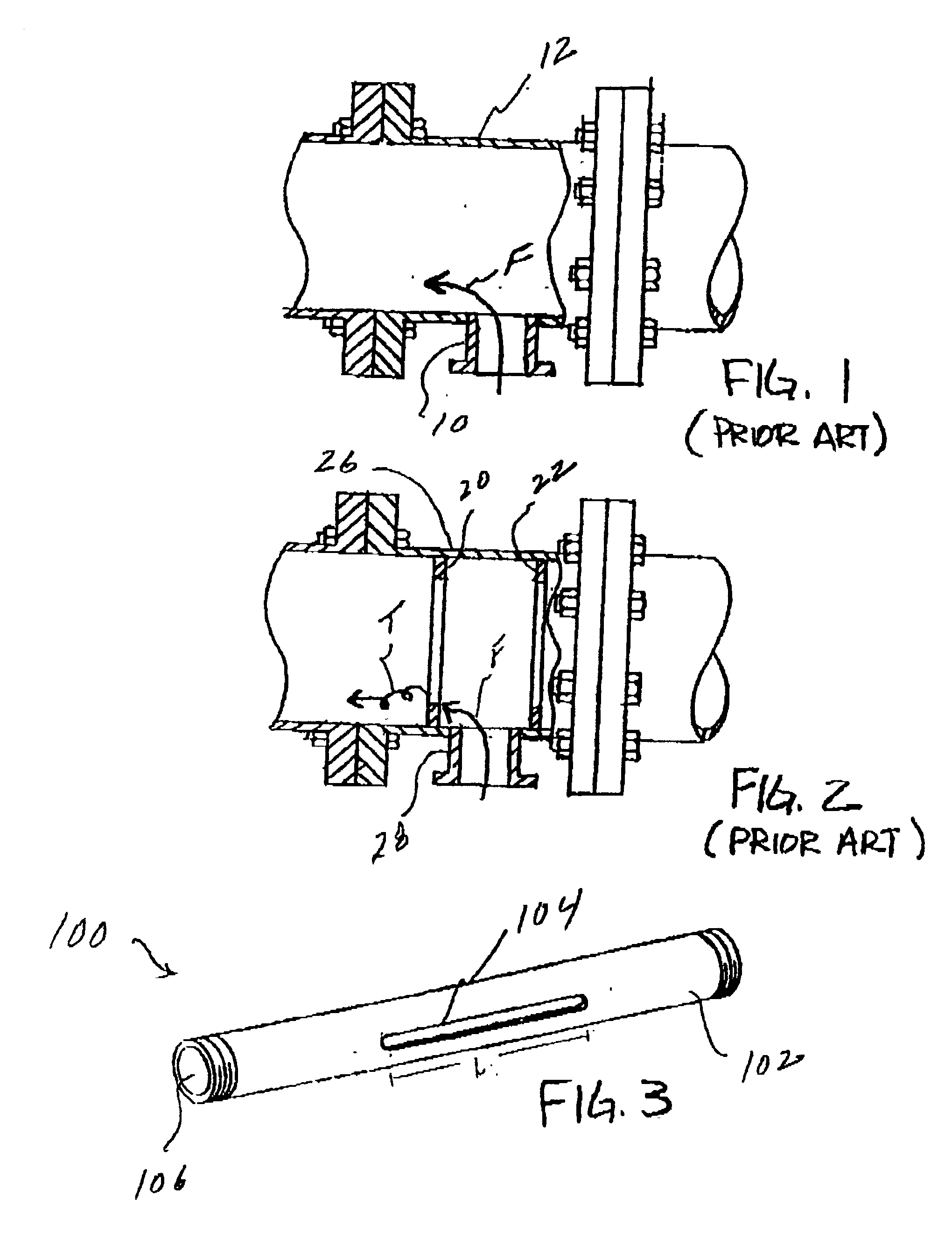
[0020] FIG. 3 shows a slotted injection pipe generally indicated as 100 having an outer surface 102 with a long narrow slot 104 therein and one or more openings 106 according to the present invention.

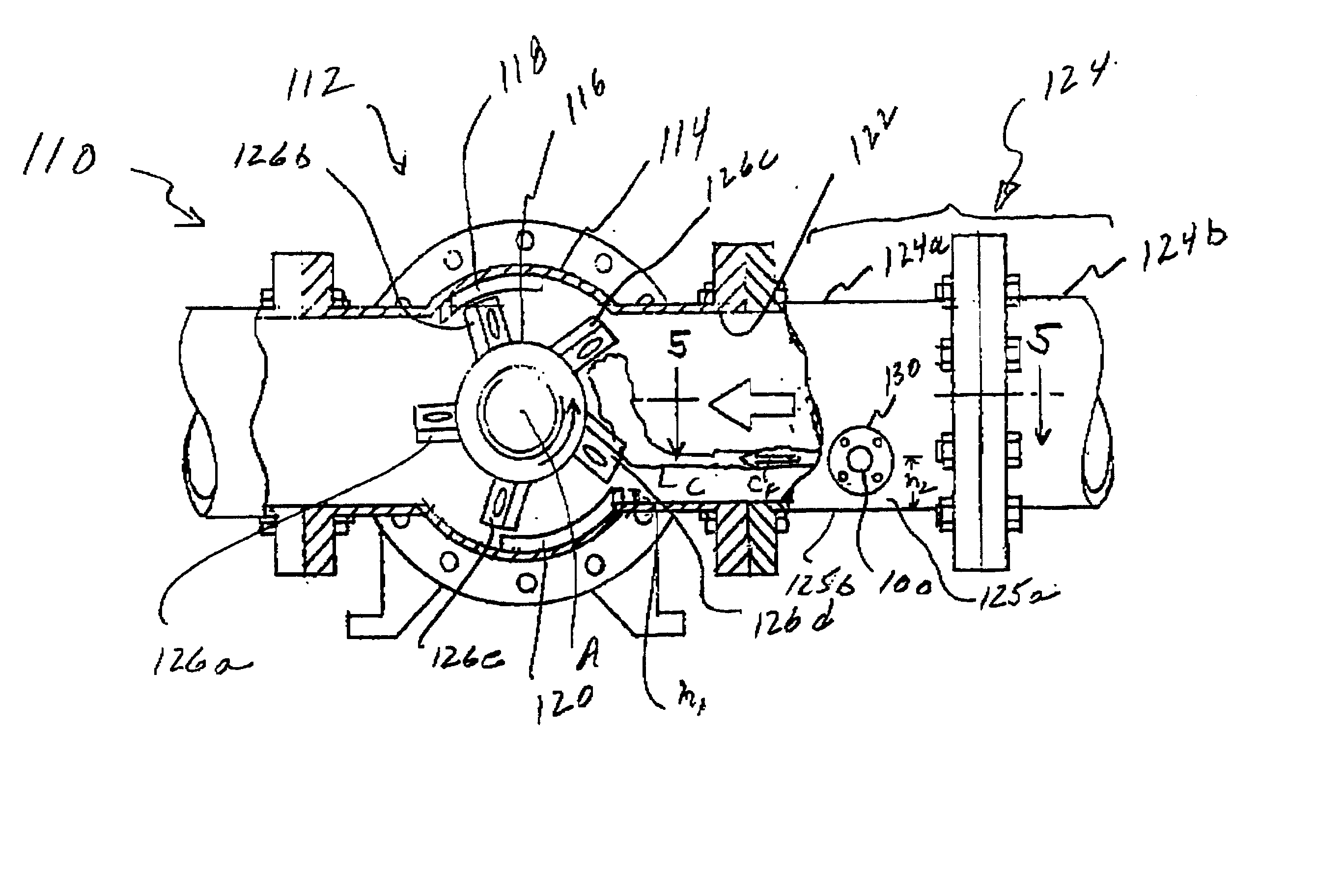
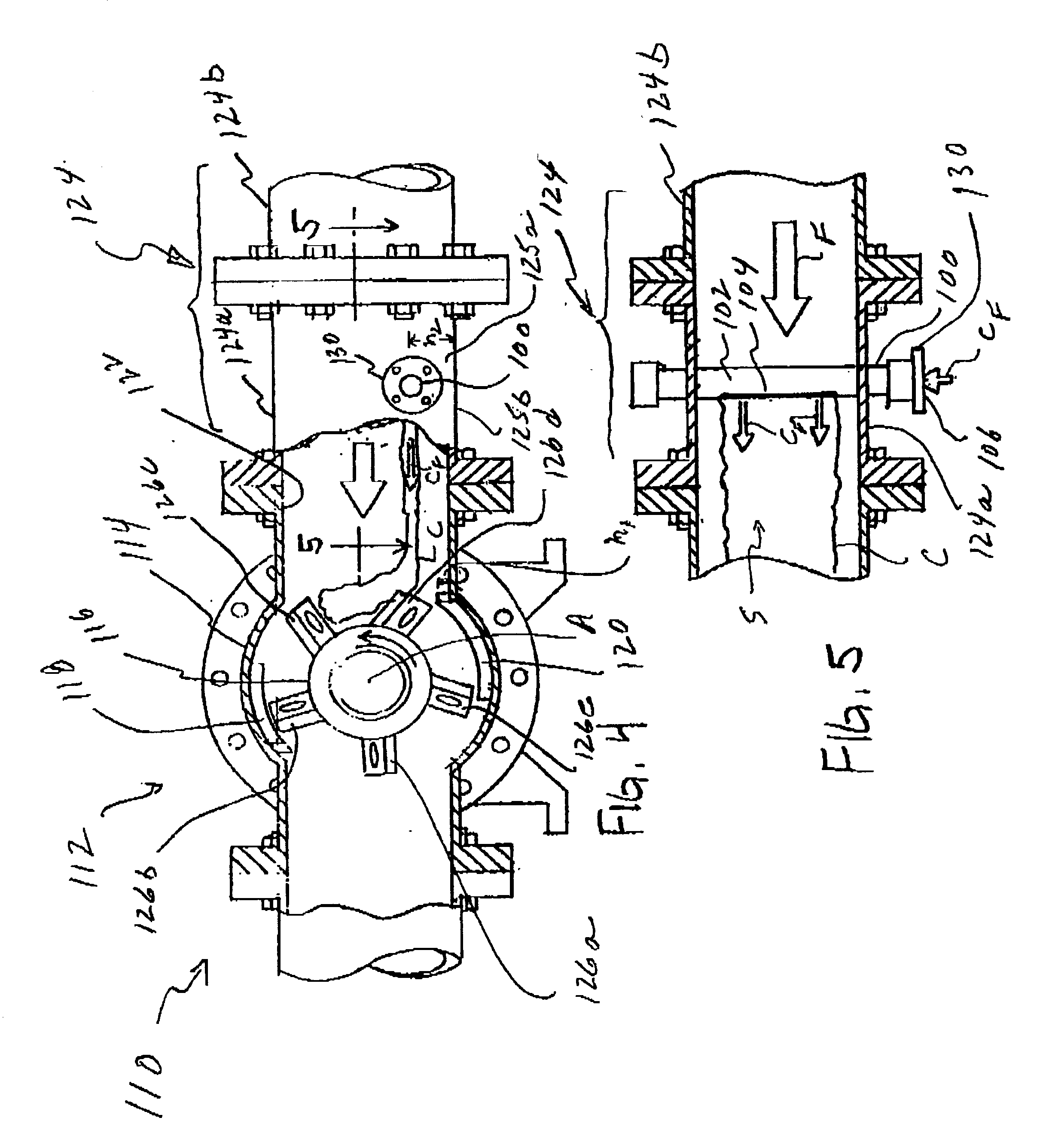
[0021] FIG. 4 shows an inline mixer and process pipe combination generally indicated as 110 having an inline mixer generally indicated as 112 with a casing 114 and a rotor 116 arranged therein. The casing 112 has one or more stationary vanes 118, 120 and an inlet 122 connected to a process pipe configuration 124. For the purpose of describing the invention, the process pipe configuration 124 is shown and described as including two pipes, i.e. a chemical injection pipe 124a and a main process pipe 124b, each having flanges for coupling together with a bolting arrangement. The chemical injection pipe 124a is arranged between the main process pipe 124b and an inlet 122 of the inline mixer 112, and similarly coupled thereto. The rotor 116 has one or more rotary vanes 126a, 126b, 126c, 126d,...


PUM


Abstract

A new and unique inline mixer and process pipe combination includes an inline mixer with a casing and a rotor arranged therein. The casing has one or more stationary vanes and an inlet connected to a process pipe configuration. The rotor has one or more rotary vanes that rotate on an axis of rotation in the casing. The process pipe configuration includes a chemical injection pipe having a slotted injection pipe arranged therein having an outer surface with a long narrow slot therein oriented substantially parallel to the axis of rotation of the rotor for injecting a chemical into a process flow media flowing in the process pipe configuration. The long narrow slot is located on a downstream side of the outer surface and oriented in a plane parallel to the direction of flow of the process media.

Description

[0001] 1. Field of Invention[0002] The present invention relates to a method and apparatus for injecting a chemical into a process flow media; and more particularly relates to a method and apparatus for injecting a chemical into a process flow media upstream of an inline mixer.[0003] 2. Description of Related Art[0004] FIG. 1 shows a simple method of injecting a chemical into a process flow media upstream of a dynamic mixer (see FIG. 4) in which the chemical flow generally indicated as F is introduced using a pipe 10 that joins a main process piping 12 in a perpendicular or angled fashion. Generally, the chemical injection piping 10 is arranged perpendicular to the main process piping 12 and is smaller in diameter than the main process piping 12. The chemical injection piping 10 may be introduced anywhere around the circumference of the main process piping 12 (i.e. the bottom, top or side). However, the method of adding the chemical flow using a perpendicular or angled connection do...

Claims


Application Information

Patent Timeline
Patent Type & Authority Applications(United States)
IPC IPC(8): B01F5/04B01F5/06B01F7/00
CPCB01F5/0451B01F5/047B01F2215/0427B01F7/003B01F7/00908B01F5/061B01F25/31334B01F25/3131B01F25/431B01F27/11251B01F27/50
Inventor CAPPELLINO, CHARLES A.
Owner ITT MFG ENTERPRISES LLC
Why Eureka
Try Eureka