Impeller exhaust ridge vent

a technology of ridge vents and impellers, which is applied in the field of attic ventilation systems, can solve the problems of cumbersome installation, lack of ventilation of moist humid, and numerous problems inherent in ventilation systems, and achieve the effect of efficient ventilation

Active Publication Date: 2008-05-15
BMIC LLC
View PDF22 Cites 36 Cited by
  • Summary
  • Abstract
  • Description
  • Claims
  • Application Information

AI Technical Summary

Benefits of technology

[0008]Briefly described, the present invention, in one preferred embodiment, comprises an impeller exhaust ridge vent designed to extend along and cover an open ridge slot along the ridge of a roof. The ride vent includes a laterally flexible central panel having edge portions and a width sufficient to span and cover the ridge slot. Depending standoffs or supports can be formed on the bottom of the central panel for supporting the central panel above and spaced from the roof deck. A base panel spaced from the central panel may be provided to cover the roof deck and form a smooth substantially sealed air duct between the base panel and the central panel. Vents are thereby formed along the edge portions and vent louvers cover the vents to allow air to escape from beneath the central panel while inhibiting debris and pests from entering. Upstanding wind baffles are disposed outboard of and spaced from the vents and extend along the ridge vent to define a trough between the edges of the central panel and the wind baffles. At least one tangential impeller has a plurality of impeller blades and is rotatably mounted in the trough with its axis of rotation extending generally along the length of the ridge vent. The tangential impeller combined with the edge of the central panel on one side and the upstanding wind baffle on the other form a “cross-flow fan” adjacent the vent. Rotation of the tangential impeller creates a displaced stable vortex according to the principles of cross-flow fan operation. The displaced vortex, in turn, causes air to be drawn from beneath the central panel, and thus out of the attic through the ridge slot. The air is then exhausted, also according to the principles of cross-flow fan operation, up and away from the trough in which the impeller is mounted. Accordingly, the rotating tangential impeller transforms the otherwise passive ridge vent into an active ventilation system that forcibly draws air out of the attic below.
[0009]In one embodiment, the tangential impeller is mounted for free rotational movement within the trough. With this embodiment, the force of a breeze blowing across the roof and over the ridge vent causes the tangential impeller to spin, thus generating the active suction of air from the attic. In another embodiment, the tangential impeller is coupled to a small electric motor, which rotates the tangential impeller when activated. The electric motor can be powered by any suitable source of electricity such as, for example, the building's electrical service, a solar panel, batteries, a wind generator, or combinations thereof. In any event, activation of the electric motor preferably is controlled by a controller that receives signals from temperature and humidity sensors within the attic. The controller is configured to activate the electric motor, and thus to spin the tangential fan, upon the occurrence of predetermined temperature and humidity conditions within the attic. With this powered embodiment of the invention, air can be forcibly drawn out of the attic without regard to the presence of an outside breeze or the presence of hot attic air to drive convection based ventilation. Thus, efficient ventilation can be accomplished when there is no breeze or when the breeze happens to be blowing along the length of the ridge vent. Equally importantly, attic ventilation can be achieved under conditions where passive ridge vents provide little or no ventilation. For example, if the attic air is too cool to drive convection based ventilation, but it nevertheless is desirable to ventilate the attic because of high humidity conditions therein, the motor of the present invention can be activated to draw the humid air out of the attic through the ridge slot. Other conditions may exist in which active ventilation can be accomplished with the present invention under circumstances where natural ventilation might not otherwise occur.
[0010]Thus, a novel new ridge vent is now provided that successfully addresses the problems and shortcomings of prior art ridge vents discussed above. These and other features and advantages of the present invention will become more apparent upon review of the detailed description set forth below, when taken in conjunction with the accompanying drawing figures, which are briefly described as follows.

Problems solved by technology

While the latter more sophisticated types of ridge vents have proven quite successful at ventilating an attic, they nevertheless are plagued with numerous problems and shortcomings inherent in their designs.
While this is reasonably effective for ventilating hot attics, it does not provide much ventilation of the moist humid air that can form in cooler attics where there may be little or no heat induced convection.
Such attempts may be useful, but can be complex, cumbersome to install, difficult to maintain, and less effective than desired.

Method used


Image

  • Impeller exhaust ridge vent
  • Impeller exhaust ridge vent
  • Impeller exhaust ridge vent

Examples


Embodiment Construction

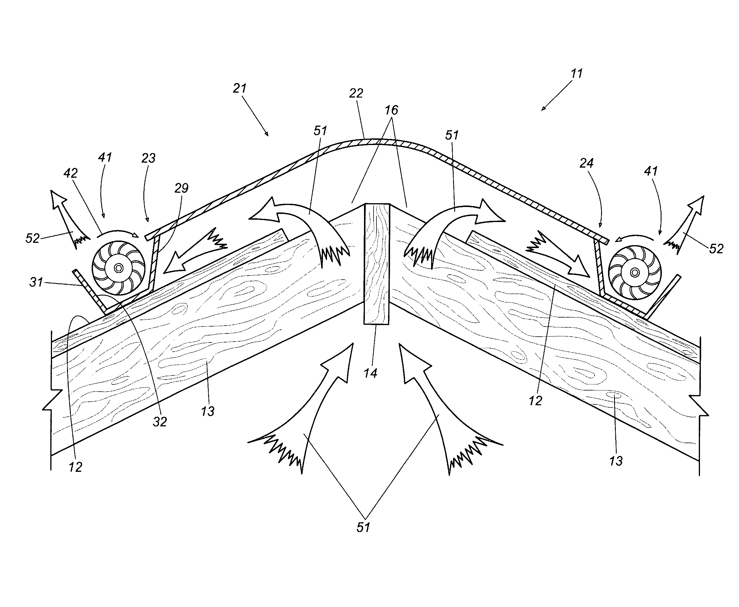
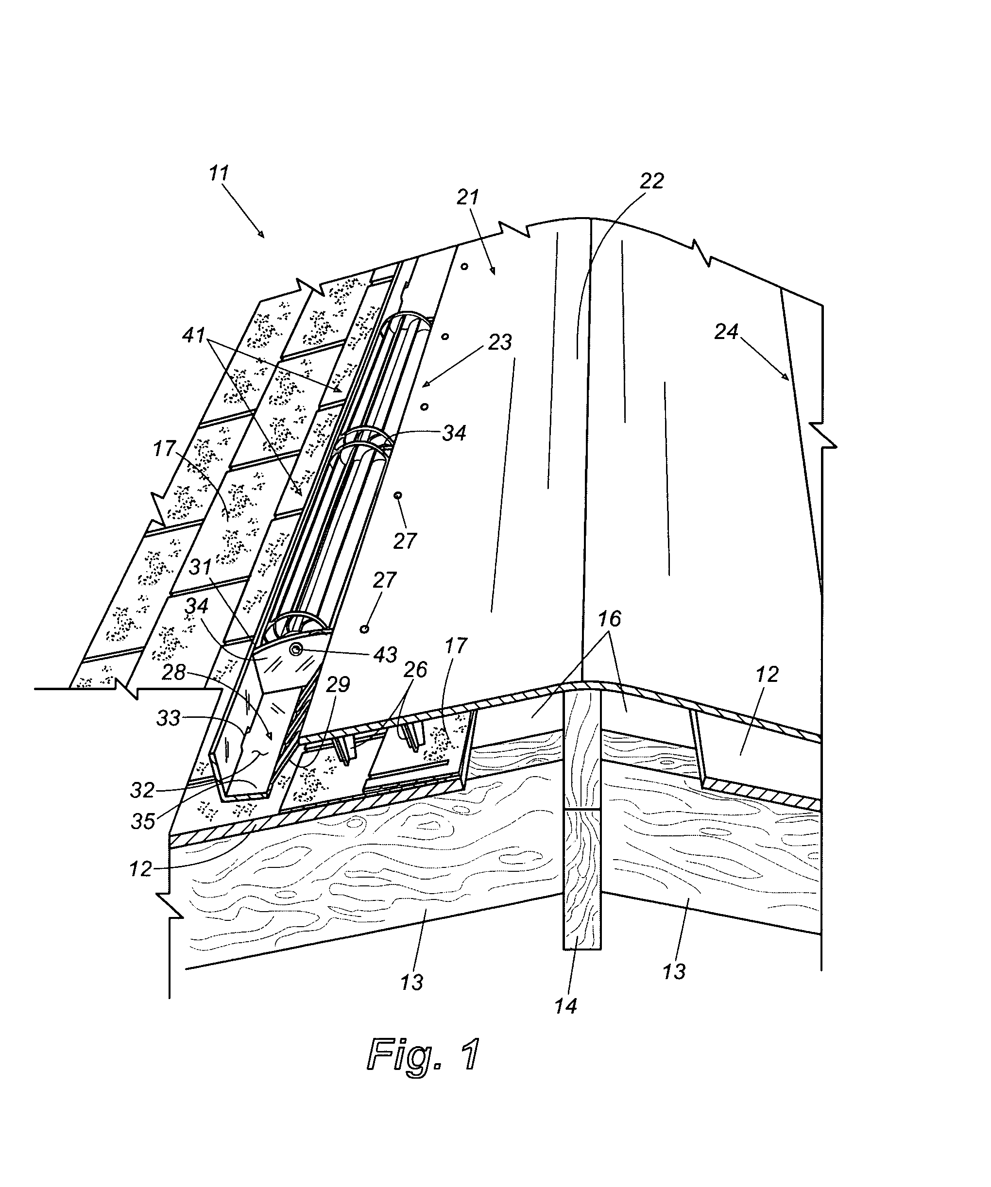
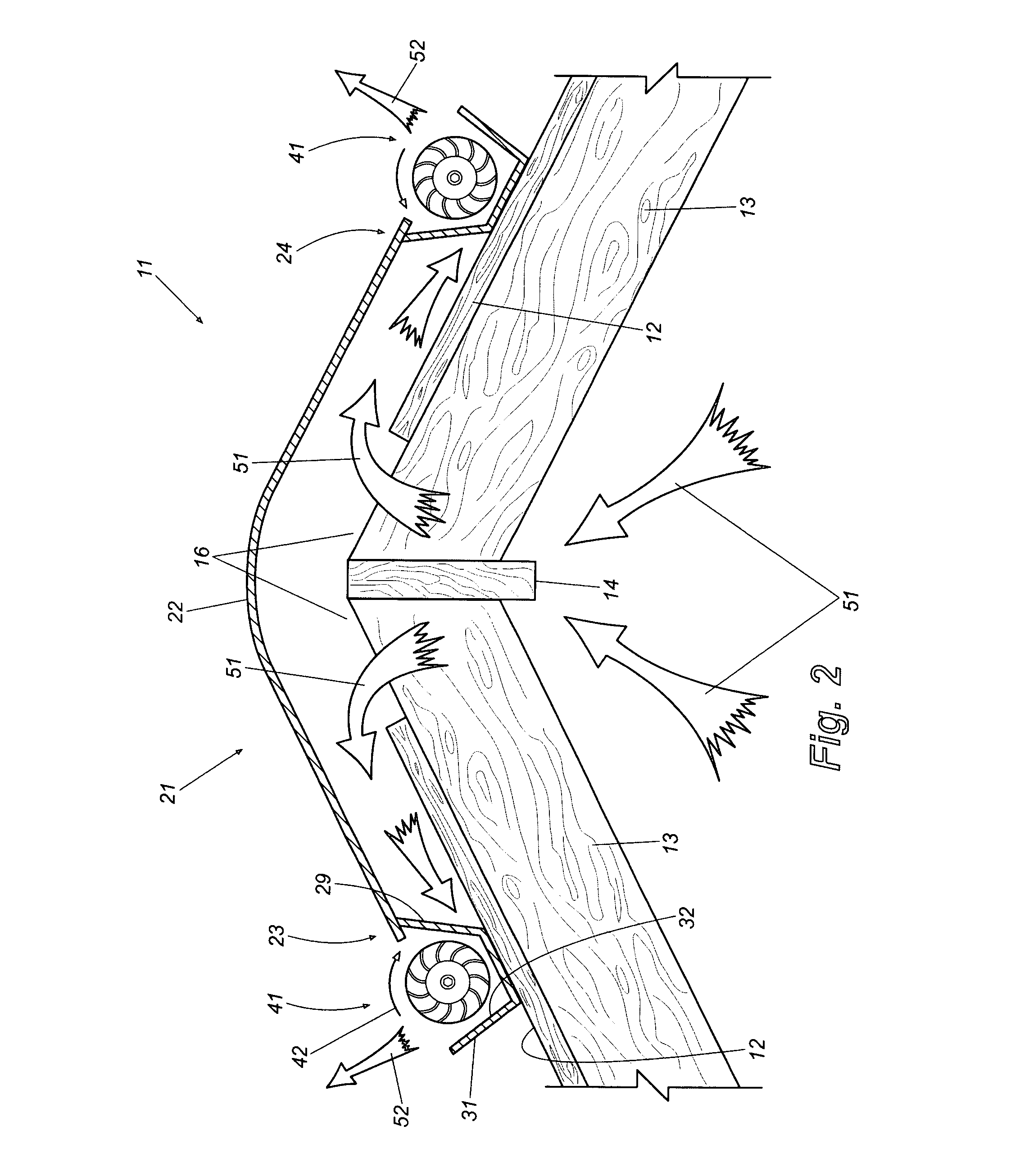
[0018]FIG. 1 is a perspective partially sectional view of an impeller exhaust ridge vent of this invention installed on the ridge of a roof. It will be understood that while only a short section of the ridge vent is shown in FIG. 1, the ridge vent preferably extends along a substantial portion of the length of the roof ridge. This may be accomplished by attaching shorter ridge vent sections end to end along the ridge, or by using a continuous rolled ridge vent configuration as is known in the art. Further, while only one side of the ridge vent is depicted in FIG. 1, the non-visible side is substantially a mirror image thereof and descriptions of elements on the visible (left) side in FIG. 1 apply equally to the non visible (right) side.

[0019]Referring in more detail to FIG. 1, the impeller exhaust ridge vent 11 is installed along the ridge of a gable roof. The roof, in this example, comprises a roof deck 12 that is supported atop rafters 13. The rafters 13 meet and are attached at a...


PUM


Abstract

An impeller exhaust ridge vent is provided for covering a ridge slot formed along the ridge of a roof. The ridge vent has an elongated laterally flexible center panel with edge portions along which vents are formed. Standoffs can depend from the bottom of the center panel for supporting the center panel a predetermined distance above the roof deck so that attic air can vent through the ridge slot, beneath the center panel, and exit through the vents. A base panel can be provided to cover the roof deck and form a smooth substantially sealed air duct for passage of the air. Upstanding wind baffles are disposed outboard of and spaced from the vents. One or more tangential impellers is rotatably mounted in the pace between the vents and wind baffles and can be free spinning or driven by an electric motor. Rotation of the tangential impellers creates a cross-flow fan effect that draws air forcibly from beneath the center panel and exhausts it to ambience. The attic space is thereby actively ventilated.

Description

TECHNICAL FIELD[0001]This invention relates generally to attic ventilation systems and more specifically to ridge vents.BACKGROUND[0002]It is important in modern buildings such as homes and offices that the attic space of the building be well ventilated. Attic ventilation reduces the searing heat that can build up in the attic during summer months, thereby reducing substantially the cooling costs and other problems associated with the attic heat. It is equally important that moist air be removed from the attic to reduce and control humidity, which otherwise can result in mold, mildew, and rot within the attic and living spaces. Removal of heat and humidity from attic spaces traditionally has been accomplished with attic ventilation systems of various designs. Such systems include, for example, simple gable vents to promote cross-ventilation through the attic, static roof vents located at strategic positions along the slope of a roof, and active attic ventilation systems, which usual...

Claims


Application Information

Patent Timeline
Patent Type & Authority Applications(United States)
IPC IPC(8): F24F7/02F24F7/06F24F13/20
CPCF24F7/025F24F11/0015F24F11/0001F24F11/30F24F2110/20F24F11/49
Inventor CHICH, ADEMRAILKAR, SUDHIRZARATE, WALTERDUFFY, BRIAN
Owner BMIC LLC
Why Eureka
Try Eureka