Method of Normal Direction Finding Based on Parallel Mechanism

A parallel, end-effector technology, used in metal processing mechanical parts, metal processing, automatic control devices, etc., can solve the problems of difficult adjustment, limited adjustment range, and high requirements for testing equipment, and can meet the requirements of hole-making accuracy and accurate method. The effect of alignment and high stiffness to weight ratio

Active Publication Date: 2017-01-04
NANJING UNIV OF AERONAUTICS & ASTRONAUTICS +1
View PDF10 Cites 0 Cited by
  • Summary
  • Abstract
  • Description
  • Claims
  • Application Information

AI Technical Summary

Problems solved by technology

[0004] In November 2007, "Acta Aeronautics" No. 06, pages 1455-1459, published a three-point fast leveling algorithm for large-scale wallboard CNC drilling and riveting with authors Qin Xiansheng, Wang Wendan and Wei Teng, which described a A normal attitude adjustment method that adjusts the product attitude through the CNC bracket to make the tool axis consistent with the normal direction at the processing position. This method uses three displacement sensors installed on the power head of the riveting machine to detect the normal deviation. In order to achieve the purpose of normal alignment based on the calculation of the adjustment amount of each adjustment axis of the bracket, the disadvantage is that the aircraft parts are generally large in size and complex in structure, and it is difficult to adjust and the adjustment range is limited. Structural rigidity and control precision put forward higher requirements
[0005] On November 20, 2013, the Chinese invention patent CN 102284956 B disclosed a normal alignment method for an automatic drilling and riveting robot, which calculates the tool axis and the hole-making position through the detection and calculation of four laser displacement sensors installed on the end effector. The deviation of the normal direction is used as a basis to calculate the adjustment amount of the 6 joints of the robot, so as to adjust the consistency between the tool axis and the normal direction of the skin. This attitude adjustment method is mainly used for the assembly of small parts such as aircraft wing parts and vertical tails. Normal attitude adjustment during hole making, but for the hole making at the butt joints of large aircraft such as the C919 fuselage, this floor-mounted assembly system cannot meet the requirements
[0006] On March 28, 2012, the Chinese invention patent CN101957175B disclosed a method based on a three-point micro-plane normal direction detection method, which uses a plane approximation instead of a micro-curved surface, and applies laser displacement sensor technology and data acquisition technology, through a certain algorithm The method of measuring the normal vector of the point to be measured on the surface, the shortcoming of this detection method is that the sensor needs to use the sensor to collect 30 measurement points on the proposed spherical surface to calibrate the attitude parameters of the laser displacement sensor during the normal detection process, so that It will complicate the calculation process and cannot be applied to the normal alignment of the end effector of the automatic drilling and riveting system
[0007] In the 7th issue of "Modern Manufacturing Engineering" in 2010, the authors Xie Youjin, Wang Zhongqi, Kang Yonggang, and Ying Gaoming's research on the algorithm for solving the normal vector of the deformed surface by spherical approximation was published. The spherical approximation described by it can solve the normal vector of the deformed surface. Solve the problem of solving the loss vector of the surface point method in real time, but this measurement method, like the traditional detection method, has the disadvantages of high requirements for detection equipment, large amount of data collection, complex data processing, and long time-consuming

Method used


Image

  • Method of Normal Direction Finding Based on Parallel Mechanism
  • Method of Normal Direction Finding Based on Parallel Mechanism
  • Method of Normal Direction Finding Based on Parallel Mechanism

Examples


Embodiment Construction

[0023] The present invention will be described in further detail below in conjunction with the accompanying drawings.

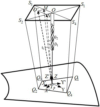
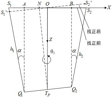
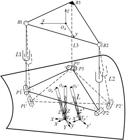
[0024] The device used in the normal alignment method based on the parallel mechanism of the present invention includes a parallel mechanism, a cross slide, four laser displacement sensors and an end effector, and the whole device is controlled and adjusted by a drilling riveting system controller. The above-mentioned parallel mechanism has two degrees of freedom of rotation, including a fixed platform and a moving platform. The fixed platform and the moving platform are connected by two telescopic rods and a fixed rod. The movable platform is connected, the telescopic rod is connected with the fixed platform through the spherical pair, the fixed rod is fixedly connected with the fixed platform, and its branch chain constitutes the SPU structure. Four laser displacement sensors are installed on the end effector, and the end effector is installed on the moving...


PUM


Abstract

The invention discloses a normal direction alignment method based on a parallel mechanism, which belongs to the field of normal direction precision control. The device used in the present invention includes a parallel mechanism, a cross slide, four laser displacement sensors, and an end effector; the parallel mechanism includes a fixed platform and a moving platform connected by connecting rods, and the end effector is installed on the moving platform of the parallel mechanism. The fixed platform of the mechanism is installed on the cross slide, and the laser displacement sensor is installed on the end effector; the method first establishes the coordinate system of the parallel mechanism and the tool coordinate system, and the distance value detected by the laser displacement sensor is used to calculate that the end effector should be adjusted to The desired normal posture; finally, the adjustment amount of the parallel mechanism is obtained through the inverse solution of the deviation from the current posture to the desired posture under the condition that the position of the virtual tool tip point remains unchanged, so as to realize the normal correction. The device used in the invention has good rigidity, large bearing capacity, simple inverse solution algorithm and high precision, and can quickly realize the normal alignment of the end effector.

Description

technical field [0001] The invention relates to a normal alignment method, in particular to a normal alignment method based on a parallel mechanism, and belongs to the field of normal accuracy control. Background technique [0002] The assembly of aircraft parts is mainly realized by riveting. The quality of riveting directly affects the performance and safety of the aircraft. Therefore, riveting is a very important process in the aircraft manufacturing process. The hole-making accuracy before riveting plays a decisive role in the quality of riveting, especially the degree to which the axial direction of the tool is consistent with the normal direction of the position where the hole is to be made on the skin during hole making. Therefore, the attitude of the product or the tool must be adjusted before making the hole to ensure the vertical accuracy between the tool axis and the hole making position. [0003] At present, there are two ways to adjust the normal posture of the...

Claims


Application Information

Patent Timeline
Patent Type & Authority Patents(China)
IPC IPC(8): B23Q15/26
Inventor 田威廖文和韩锋张旋王丽峰袁磊余斌张斌斌
Owner NANJING UNIV OF AERONAUTICS & ASTRONAUTICS
Why Eureka
Try Eureka