Detection device for profile and hole location of car sunroof

A hole position detection, skylight type technology, applied in the direction of measuring device, mechanical measuring device, using mechanical device, etc., can solve the problem of detection efficiency affecting production speed, etc., to achieve a firm and reliable structure, improve detection efficiency, and prevent displacement and change. Effect

Active Publication Date: 2015-03-04
WUHU MOTIONTEC AUTOMOTIVE
10 Cites 9 Cited by

AI-Extracted Technical Summary

Problems solved by technology

Although the three coordinates can be detected normally, they need to be inspected at the beginning, middle, and end of each day, and there are random random inspectio...

Method used

By opening the glass surface difference detection mechanism 3, the profile block 6, pull out the main and auxiliary positioning pins, the hole position detection pin 7, the skylight is placed on the detection device, then insert the main and auxiliary pins, to limit the skylight x , the degree of freedom in the Y direction, use the detection pin to detect the position of the sunroof installation hole, use the glass surface difference detection mechanism 3 to detect the glass surface and the theoretical value, and check the matching ...

Abstract

The invention discloses a detection device for the profile and the hole location of a car sunroof. The device comprises a bottom plate on which an overturning mechanism is arranged; the car sunroof is mounted on the overturning mechanism; glass profile difference detecting mechanisms are arranged like a rectangle on the bottom plate; a main positioning pin is arranged beside the glass profile difference detecting mechanism at the left side; profile cushion blocks are arranged inside the glass profile difference detecting mechanism, and while profile blocks are arranged on the glass profile difference detecting mechanism; a hole location detecting pin is arranged on the glass profile difference detecting mechanism at the lower side; a draining port detecting block is arranged at the lower side of the bottom plate; when in use, the glass profile difference detecting mechanisms are opened, the profile blocks are overturned to reach the opening position, then main, secondary positioning pins and the hole location detecting pin are drawn out, the sunroof is positioned to the detecting device, then the main and secondary positioning pins are inserted, and finally the profile difference and the hole location can be detected. The detection device is simple in structure, convenient to mount and dismount, and is able to effectively improve the detection efficiency.

Application Domain

Mechanical counters/curvatures measurements

Technology Topic

CushionEngineering +1

Image

  • Detection device for profile and hole location of car sunroof
  • Detection device for profile and hole location of car sunroof

Examples

  • Experimental program(1)

Example Embodiment

[0013] In order to deepen the understanding of the present invention, the present invention will be described in further detail below in conjunction with examples. The examples are only used to explain the present invention and do not constitute a limitation on the protection scope of the present invention.
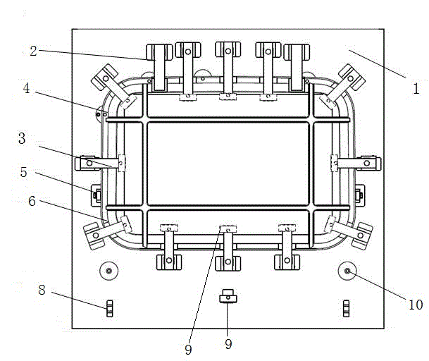
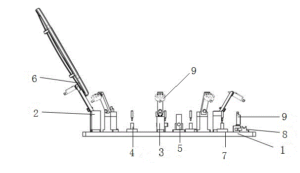
[0014] Such as figure 1 , 2 As shown, this embodiment provides an automobile sunroof profile and hole position detection device, which includes a bottom plate 1, on which a turning mechanism 2 is provided, and the automobile sunroof is fixed on the turning mechanism 2, on the bottom plate 1 A glass level difference detection mechanism 3 is provided, and the glass level difference detection mechanism 3 is arranged in a rectangular shape on the bottom plate 1, and a main positioning pin 4 is provided beside the glass level difference detection mechanism 3 on the left side. The detection mechanism 3 is provided with a profile pad 5, the glass surface difference detection mechanism 3 is provided with a profile block 6, and the lower glass surface difference detection mechanism 3 is provided with a hole position detection pin 7, so A water outlet detection block 8 is provided on the lower side of the bottom plate 1. The turning mechanism 2 and the profile block 6 are connected by screws, the turning mechanism 2 is fixed on the bottom plate 1, and the turning sunroof is placed on the profile pad during detection. The glass surface difference detection mechanism 3 is provided with a digital display dial gauge 9 which can measure the profile values ​​of various parts of the skylight. The material of the whole device is aluminum alloy. The lower side of the bottom plate 1 is provided with a left-right symmetrical auxiliary positioning pin 10.
[0015] By opening the glass surface difference detection mechanism 3 and the profile block 6, pull out the main and auxiliary positioning pins and the hole position detection pin 7, place the skylight on the detection device, and then insert the main and auxiliary pins to limit the X and Y directions of the skylight For the degree of freedom, the detection pin is used to detect the position of the sunroof installation hole, the glass surface difference detection mechanism 3 is used to detect the glass surface and the theoretical value, and the matching effect of the sunroof and the whole vehicle is checked. The device has a firm and reliable structure, can accurately locate the skylight, prevents the skylight from displacement and change during the detection process, has a simple structure, is convenient for assembly and disassembly, and can effectively improve the detection efficiency. The invention has a simple structure, can quickly, conveniently and reliably detect face difference and hole position of the skylight, and improve the detection efficiency.

PUM

no PUM

Description & Claims & Application Information

We can also present the details of the Description, Claims and Application information to help users get a comprehensive understanding of the technical details of the patent, such as background art, summary of invention, brief description of drawings, description of embodiments, and other original content. On the other hand, users can also determine the specific scope of protection of the technology through the list of claims; as well as understand the changes in the life cycle of the technology with the presentation of the patent timeline. Login to view more.

Similar technology patents

Lacquer stirring barrel capable of accurately controlling discharging amount and working method thereof

PendingCN107930471Asolid structuresecure installation
Owner:WENZHOU KAMARY LATEX PROD

Steel cofferdam caisson

PendingCN111501803Asolid structureImprove water tightness
Owner:QINGDAO PORT INT +2

Classification and recommendation of technical efficacy words

  • solid structure

Intelligent spiral lifting tower three-dimensional garage

InactiveCN102277991Asolid structureReduce failure
Owner:李忠礼

Cutting bed

ActiveCN102658564Asolid structureeasy leveling
Owner:HANGZHOU ECHO SCI TECH

Shockproof projection LED lamp

PendingCN107166192Asolid structureGood shock resistance
Owner:广东爱奇光电科技有限公司

Vehicle saucer device

ActiveCN104943592Asolid structure
Owner:BAOJI HUSN ENG VEHICLE
Why Eureka
Try Eureka