Transmit-receive split planar array phased-array radar antenna array and beam former

A phased-array radar with separated transceiver technology, which is applied in the radar field to achieve the effects of reduced structural design costs, reduced number of components, and increased reliability

Active Publication Date: 2015-03-04
CNGC INST NO 206 OF CHINA ARMS IND GRP
View PDF4 Cites 33 Cited by
  • Summary
  • Abstract
  • Description
  • Claims
  • Application Information

AI Technical Summary

Problems solved by technology

[0005] Literature (Zhang Shuai et al. Small array extrapolation calculation and synthesis method of radiation pattern of large planar array antenna, Computational Physics, 2011, 28(4), 554-560 ) and so on, proposed a method for op

Method used


Image

  • Transmit-receive split planar array phased-array radar antenna array and beam former
  • Transmit-receive split planar array phased-array radar antenna array and beam former
  • Transmit-receive split planar array phased-array radar antenna array and beam former

Examples


Embodiment Construction

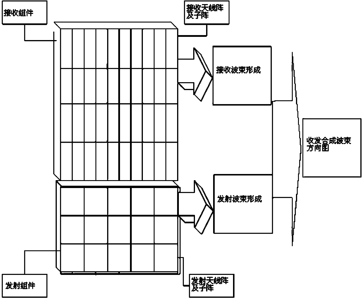
[0075] Design the S-band two-dimensional active phased array radar according to figure 2 , the radar antenna adopts the form of sending and receiving separate arrays. The large transmitting array includes 32 transmitting sub-arrays, which are arranged at an even interval of 4 rows and 8 columns. The columns are evenly spaced above the antenna array.

[0076] refer to Figure 4 , the number and arrangement of array elements in the transceiver sub-array are different. Among them, the transmitting sub-array has a total of 9 array elements, which are arranged in a 3×3 arrangement. The sub-array has a total of 8 array elements, which are arranged in a 2×4 manner, with an array element spacing of 0.048m, and a 2×4 (beam width, azimuth 50 degrees, elevation 25 degrees) sub-array.

[0077] refer to Figure 5 , the transmitting antenna sub-array is designed with a microstrip line, the array elements are arranged in 3×3, and the array elements in the sub-array are synthesized into o...


PUM


Abstract

The invention relates to a transmit-receive split planar array phased-array radar antenna array and a beam former. The method comprises designing and arranging antenna receiving arrays and transmitting arrays, connecting radar receiving assemblies with transmitting assemblies, designing beam formers of receiving large arrays and transmitting large arrays, and finally, forming synthesis scanning wave beams by use of the receiving large arrays and the transmitting large arrays, such that the problem of grid lobes generated during antenna scanning is overcome. The method is applied to low-cost design of an active phased-array radar, and is especially suitable for design of a multifunctional active phased-array radar which combines a mechanical scanning mode with an electrical scanning mode.

Description

technical field [0001] The invention belongs to the technical field of radar, and relates to a planar array phased array radar antenna array and a beam former with separate transceivers. Background technique [0002] The scanning speed of the two-dimensional phased array radar antenna is fast, and it can track multiple targets in large airspace while searching. In order to achieve good tracking of the target, high angle measurement accuracy is often required, which requires increasing the array aperture. In order to meet the condition of not generating grating lobes, the number of active components is also proportionally increased. The large phased array is not only complex in structure, but also expensive, which seriously limits the application of active phased array radar. [0003] In order to reduce the mutual coupling between array elements, the antenna array must meet certain constraints (for example, not less than a given value), but it often brings grating lobe probl...

Claims


Application Information

Patent Timeline
IPC IPC(8): G01S7/02H01Q21/00
CPCG01S7/02H01Q21/00
Inventor 强勇李万玉游俊付源谢斌黄志忠任媛媛
Owner CNGC INST NO 206 OF CHINA ARMS IND GRP
Why Eureka
Try Eureka