
Vibration suppression and friction reduction type deep hole drill bit

A deep hole drill bit and drill body technology, applied in drilling/drilling equipment, drill repair, twist drill, etc., can solve the mismatch between cutting ability and chip removal ability, edge failure of deep hole drill bit, lack of adaptability, etc. problems, to achieve the effects of reducing production and inventory costs, prolonging the life of the drill bit, and good adaptability to working conditions

Pending Publication Date: 2022-07-08
苏州沃钛工业技术有限公司
View PDF0 Cites 0 Cited by
  • Summary
  • Abstract
  • Description
  • Claims
  • Application Information

AI Technical Summary

Problems solved by technology

[0003] With the further improvement of processing efficiency, the deficiencies of traditional technical solutions are gradually emerging, which are reflected in the following aspects: ① For complex structures of workpieces, such as inclined holes and cross holes, incomplete chip shapes will lead to chip jamming and drill bits Fracture; ②The cutting ability and chip removal ability of the deep hole drill do not match. When the drill feed is increased, the chip will be blocked and the drill bit will be broken; ③The edge of the deep hole drill will fail due to the extremely high cutting heat in deep hole processing And the drill bit breaks; ④The diversity of the workpiece grades, the lack of adaptability and the lack of generalization and standardization, often use non-standard methods, which are not economical

Method used


Image

  • Vibration suppression and friction reduction type deep hole drill bit
  • Vibration suppression and friction reduction type deep hole drill bit
  • Vibration suppression and friction reduction type deep hole drill bit

Examples


Embodiment Construction

[0032] The technical solutions in the embodiments of the present invention will be clearly and completely described below with reference to the accompanying drawings in the embodiments of the present invention. Obviously, the described embodiments are only a part of the embodiments of the present invention, but not all of the embodiments. The components of the embodiments of the invention generally described and illustrated in the drawings herein may be arranged and designed in a variety of different configurations. Thus, the following detailed description of the embodiments of the invention provided in the accompanying drawings is not intended to limit the scope of the invention as claimed, but is merely representative of selected embodiments of the invention. Based on the embodiments of the present invention, all other embodiments obtained by those skilled in the art without creative work fall within the protection scope of the present invention.

[0033] It should be noted ...


PUM


Abstract

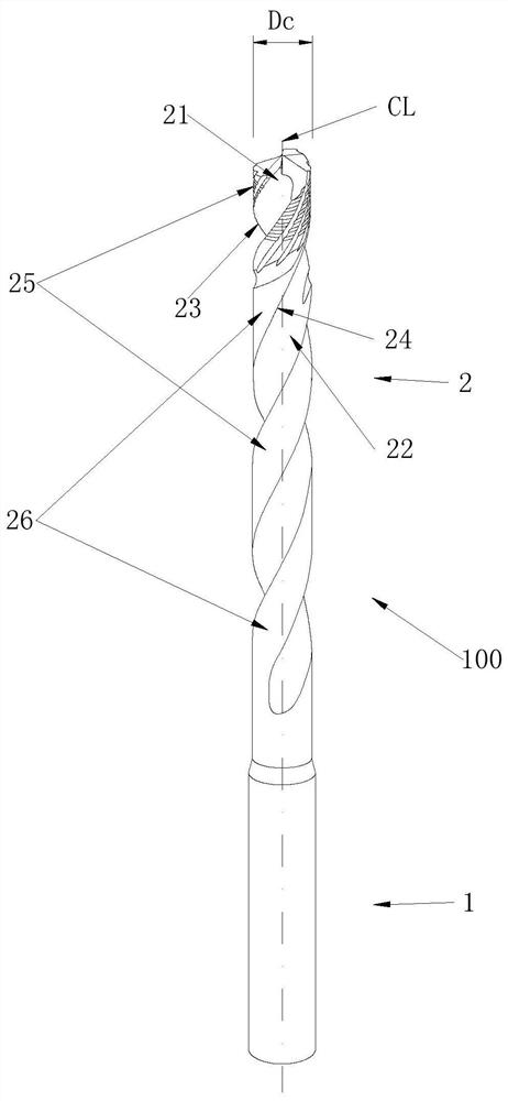
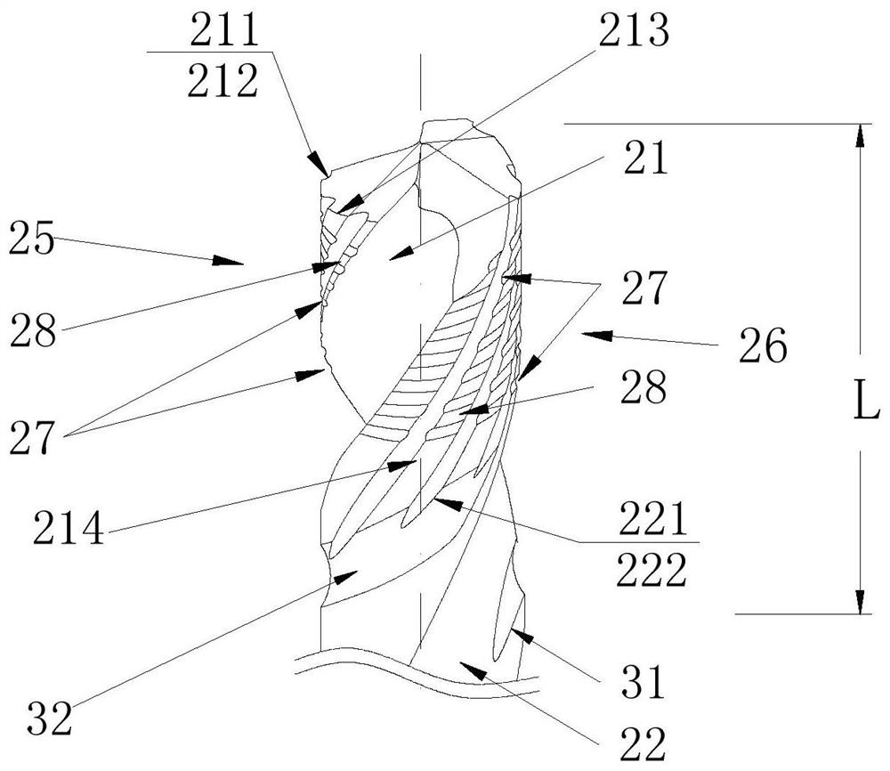
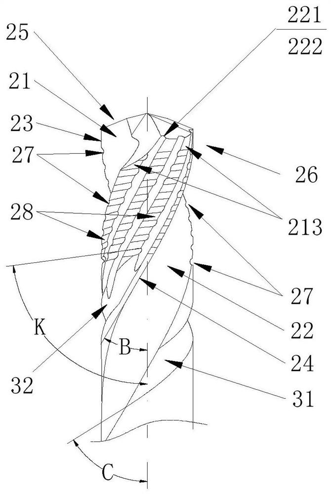
A drill body is provided with a first main chip removal groove and a second main chip removal groove, a solid part separated by the first main chip removal groove and the second main chip removal groove is a first tool back and a second tool back, and the first main chip removal groove and the second main chip removal groove form a first spiral line and a second spiral line on the outer edge of the drill body; included angles between the frontal projections of the spiral line I and the spiral line II and the axis are the spiral angles of the main chip grooves; a first chip removal auxiliary groove set and a second chip removal auxiliary groove set are formed in the first tool back and the second tool back from the position of the end face of the drill bit downwards by a certain length along the axis, and the first chip removal auxiliary groove set and the first main chip removal groove have the same spiral angle, and the second chip removal auxiliary groove set and the second main chip removal groove have the same spiral angle. The second cutter back is divided into second strip-shaped spiral blade belt sets through the first main chip removal groove, the second main chip removal groove and the first auxiliary chip removal groove set, and the first cutter back is provided with a first spiral blade belt set of the same structure as the first cutter back. A plurality of antifriction grooves which are consistent in width and are arranged in a staggered manner along the axis direction are respectively formed in the first spiral edge belt group and the second spiral edge belt group; the knife back is provided with a #-shaped reticulate pattern structure, and chip removal is smoother.

Description

technical field [0001] The invention relates to a vibration-suppressing and friction-reducing deep-hole drill bit. Background technique [0002] Carbide deep hole drills are widely used because of their high processing efficiency in small and medium-diameter deep hole machining processes such as molds, engines, and heat exchangers. [0003] With the further improvement of the demand for processing efficiency, the shortcomings of traditional technical solutions have gradually emerged, which are reflected in the following aspects: 1. For the complex structure of the workpiece, if there are inclined holes and intersecting holes, the incomplete chip shape will lead to chip blocking and the occurrence of drill bits. Fracture; ② The cutting ability and chip removal ability of the deep hole drill do not match, and when the drill feed increases, the chip will block and the drill will break; ③ Due to the extremely high cutting heat in the deep hole machining, the edge of the deep hol...

Claims


Application Information

Patent Timeline
Patent Type & Authority Applications(China)
IPC IPC(8): B23B51/02B23B51/06
CPCB23B51/02B23B51/06Y02P70/10
Inventor 刘伟
Owner 苏州沃钛工业技术有限公司
Learn More