Pull-tab-shaped bayonet lock self-locking type lead end grounding clamp

A grounding clip, self-locking technology, applied in the direction of conductive connection, clip connection conductor connection, connection, etc., can solve the problems of complex grounding clip structure, complex structure, easy to fall off, etc., to achieve convenient operation, protect life safety, Avoid the effect of accidental unlocking

Inactive Publication Date: 2015-03-04
GUANGXI UNIV
View PDF4 Cites 6 Cited by
  • Summary
  • Abstract
  • Description
  • Claims
  • Application Information

AI Technical Summary

Problems solved by technology

[0003] In order to overcome the defects existing in the prior art, the present invention provides a pull-ring type bayonet self-locking wire terminal grounding clamp, which can well solve the existing problems of complex structure and easy slippage of the existing grounding clamps
Adopting the present invention can solve the existing problems of complex structure and easy falling off of the ground wire clamp, and has broad market prospects and commercial value

Method used


Image

  • Pull-tab-shaped bayonet lock self-locking type lead end grounding clamp
  • Pull-tab-shaped bayonet lock self-locking type lead end grounding clamp
  • Pull-tab-shaped bayonet lock self-locking type lead end grounding clamp

Examples


Embodiment Construction

[0023] The specific implementation manners of the present invention will be further described in detail below in conjunction with the drawings and embodiments.

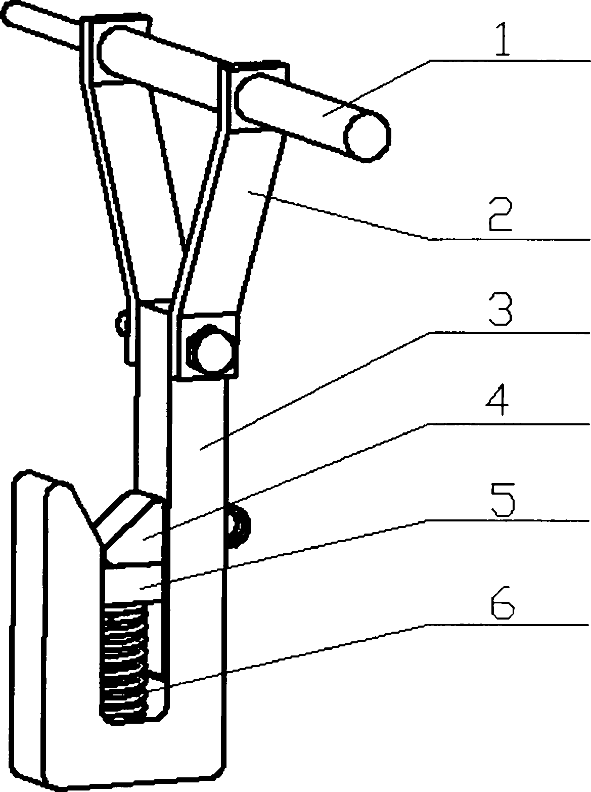
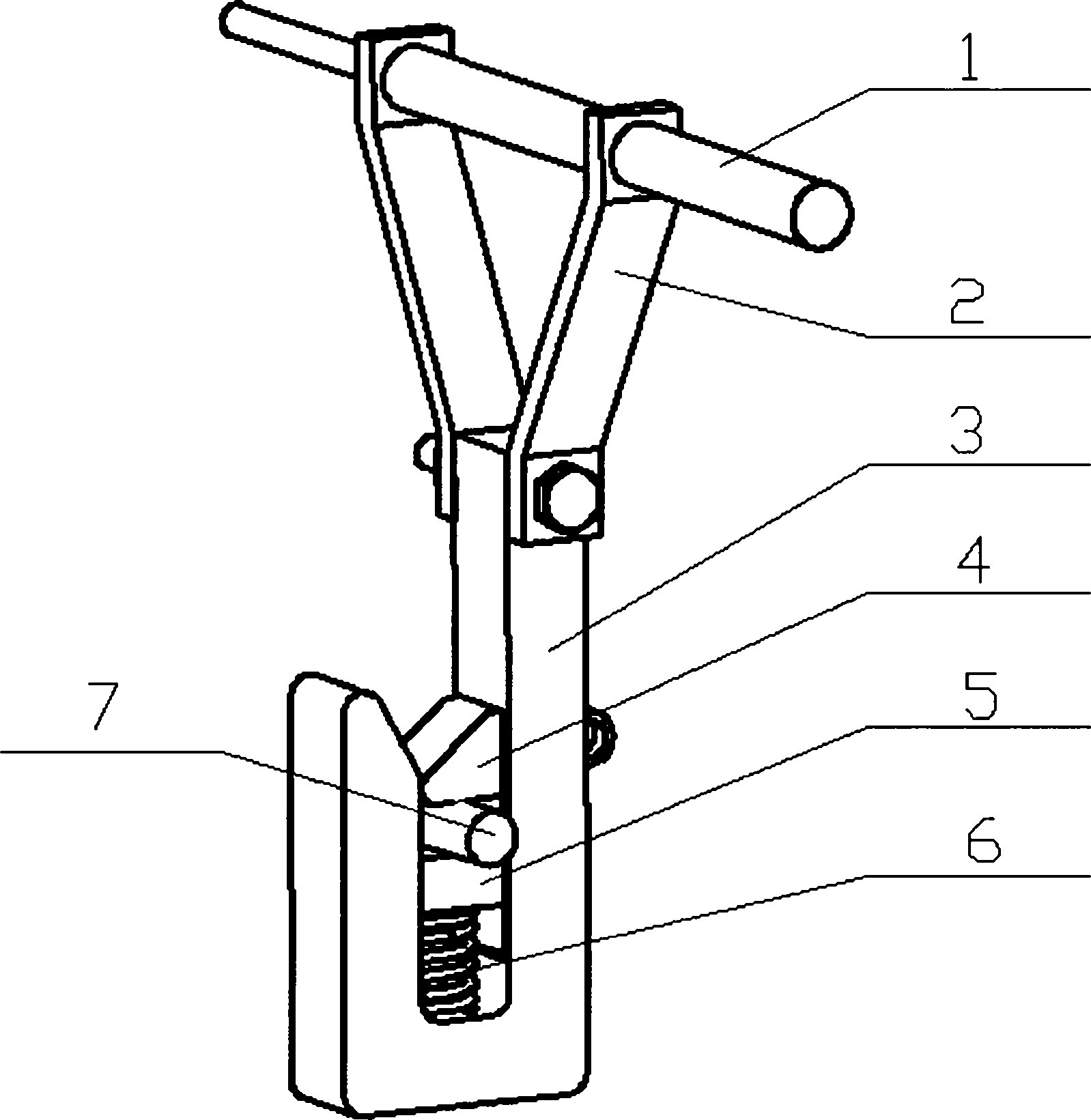
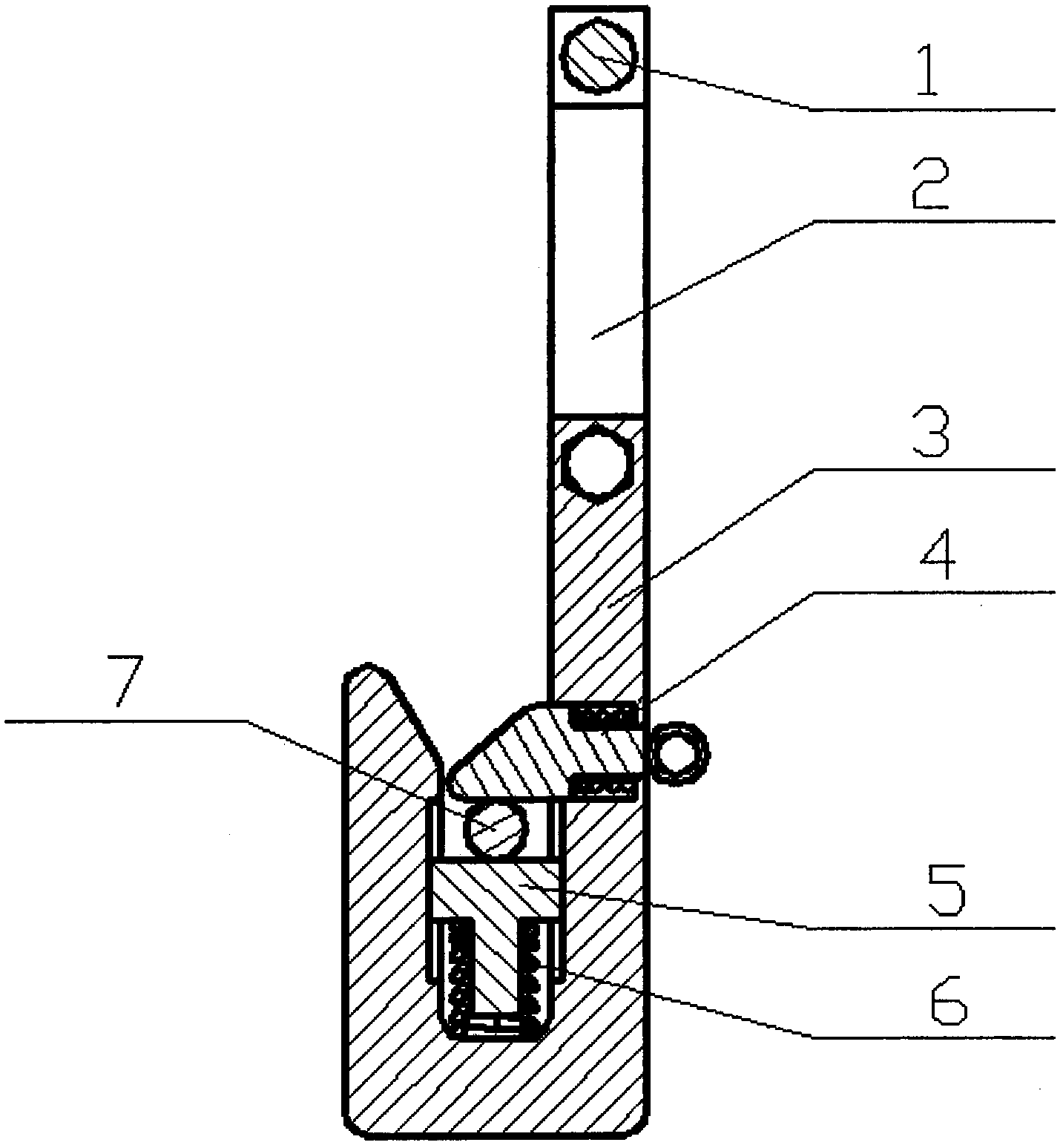
[0024] Such as figure 1 and 2 As shown, the pull ring type bayonet self-locking wire end grounding clamp of the present invention includes an operating lever 1, a Y-shaped connecting rod 2, an L-shaped clamp 3, an anti-falling mechanism 4, a T-shaped block 5 and The second compression spring 6.

[0025] The operating rod 1 is composed of a small-end cylinder 11 and a large-end cylinder 12, and the small-end cylinder 11 and the large-end cylinder 12 are connected with the upper connection hole 211 of the left curved plate 21 and the upper connection hole 221 of the right curved plate 22 of the Y-shaped connecting rod 2 . The operating rod 1 passes through the upper connecting hole 211 of the left curved plate 21 and the upper connecting hole 221 of the right curved plate 22 of the Y-shaped connecting rod 2 to suppor...


PUM


Abstract

A pull-tab-shaped bayonet lock self-locking type lead end grounding clamp comprises an operation rod, a Y-shaped connecting rod, an L-shaped clamp, a falling-prevention mechanism, a T-shaped stop block and a second compression spring, wherein the operation rod and the Y-shaped connecting rod are connected in a hung manner through connecting holes; the Y-shaped connecting rod comprises left and right bent plates, the upper part of the Y-shaped connecting rod is connected with the operation rod in the hung manner through the connecting holes, and the lower part of the Y-shaped connecting rod is connected with the L-shaped clamp through a bolt; the upper part of the L-shaped clamp is connected with the Y-shaped connecting rod through the bolt, and a groove and the falling-prevention mechanism are arranged in the L-shaped clamp; the falling-prevention mechanism comprises a pull-tab-shaped bayonet lock and a first compression spring, the first compression spring is embedded in the L-shaped clamp, and the pull-tab-shaped bayonet lock is contacted with the T-shaped stop block under the action of the first compression spring; the T-shaped stop block is sleeved with the second compression spring, the upper end of the second compression spring is contacted with the T-shaped stop block, and the lower end of the second compression spring is contacted with the L-shaped clamp. With the adoption of the grounding clamp, problems that existing grounding clamps are complex in structure, easy to fall and the like can be solved, and the grounding clamp has the broad market prospect and the high business value.

Description

technical field [0001] The invention relates to a maintenance tool for high-voltage wires, in particular to a ring-type bayonet self-locking type wire end grounding wire clamp which is convenient to operate, safe and reliable. technical background [0002] The grounding clamp at the wire end is a safety device used to temporarily short-circuit and ground the power transmission wire in a power failure. At present, the clamps used by various power grid companies mainly include double tongue type, flat type, impact type and spiral type. Yet these several clamp structures all have unreasonable parts. The double-tongue type wire clamp generally adopts the method of hooking, which is suitable for round wires. With the weight of the insulating rod itself, the top surface is pressed down on the wire, and the tongues on both sides are clamped and fixed. It is easy to use, but it is easy to slip off. The jaws of the flat type wire clamp generally apply pressure through the clamping ...

Claims


Application Information

Patent Timeline
Patent Type & Authority Applications(China)
IPC IPC(8): H01R11/14H01R11/22H01R43/027
CPCH01R11/14H01R11/22H01R43/027
Inventor 李岩舟班彩霞陈娟丽张文靖曹越
Owner GUANGXI UNIV
Why Eureka
Try Eureka