Connector assembly

A technology of connectors and plug-ins, which is applied in the field of parts and components, and can solve problems such as scratches, damages, and no protective measures

Inactive Publication Date: 2015-03-04
ANHUI JIANGHUAI AUTOMOBILE GRP CORP LTD
View PDF12 Cites 3 Cited by
  • Summary
  • Abstract
  • Description
  • Claims
  • Application Information

AI Technical Summary

Problems solved by technology

[0005] The purpose of the present invention is to provide a connector to solve the technical problem in the prior art that

Method used


Image

  • Connector assembly
  • Connector assembly
  • Connector assembly

Examples


Embodiment Construction

[0035] In order to enable those skilled in the art to better understand the technical solutions of the present invention, the present invention will be further described in detail with reference to the accompanying drawings.

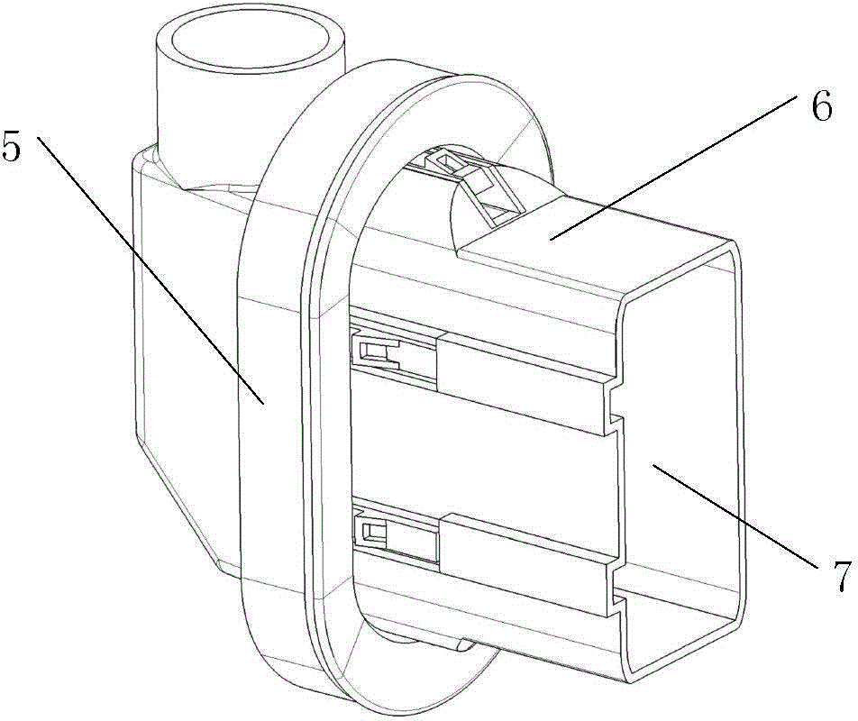
[0036] Such as Figure 3-14 As shown, a connector provided by an embodiment of the present invention includes a plug-in body 6 and a rubber sheath 5. One end of the plug-in body 6 is sleeved on one end of the rubber sheath 5, and the rubber sheath 5 and the plug-in body 6 The harness channel 7 is formed inside, the plug-in body 6 is provided with a boss 62, the rubber sheath 5 is provided with a groove 51, the boss 62 and the groove 51 cooperate to realize an inner sleeve, and the outer surface of the plug-in body 6 is also provided There is an elastic protrusion structure 61, and a clamping space is formed between the elastic protrusion structure 61 and the rubber sheath 5.

[0037] Specifically, the plug-in body 6 is used to penetrate a shielding structure...


PUM


Abstract

The invention discloses a connector assembly. The connector assembly comprises a connector assembly main body and further comprises a rubber protective sleeve, wherein one end of the connector assembly sleeves one end of the rubber protective sleeve; a wiring harness channel is formed inside the rubber protective sleeve and the connector assembly main body; a boss is formed in the connector assembly main body; a groove is formed in the rubber protective sleeve; the boss is spliced in the groove; an elastic bulge structure is further arranged on the outer surface of the connector assembly main body; and a blocking space is formed between the elastic bulge structure and the rubber protective sleeve. When the connector assembly provided by the invention is used, the large part of the connector assembly main body is positioned at one side of a shielding structure, the rubber protective sleeve is positioned at the other side of the shielding structure, and the connector assembly is blocked on the shielding structure by virtue of the blocking space between the connector assembly main body and the rubber protective sleeve, so that wiring harnesses are protected by the rubber protective sleeve after passing through the wiring harness channel inside the connector assembly, and therefore, the probability that the wiring harnesses are scratched is lowered.

Description

Technical field [0001] The present invention relates to parts, in particular to a connector. Background technique [0002] In the fields of automobiles, electronics, etc., a large number of wire harnesses need to be used. The wire harnesses usually need to penetrate through the shielding structure during the entire orientation process. [0003] figure 1 It is one of the installation diagrams of the wiring harness in the prior art, figure 2 It is the second schematic diagram of wiring harness installation in the prior art, such as figure 1 with 2 As shown, when the wire harness 1 penetrates the shielding structure 3, a through hole is opened on the shielding structure 3, a waterproof plug 2 is clamped in the through hole, and the wiring harness 1 passes through the waterproof plug 2 to penetrate the shielding structure 3. [0004] The disadvantage of the prior art is that the wire harness 1 does not take protective measures after passing through the shielding structure 3 such as shee...

Claims


Application Information

Patent Timeline
IPC IPC(8): H02G3/04H02G3/22
Inventor 孙丰超汪振兴孟胥里李荫荣王春芝王政
Owner ANHUI JIANGHUAI AUTOMOBILE GRP CORP LTD
Why Eureka
Try Eureka