Insulation fixing plate of centrifugal switch device

A technology of insulating fixed plate and centrifugal switch, which is applied in the field of dehydration, can solve the problems of unstable and reliable working performance, many fault sources, and many parts, and achieve the effect of stable and reliable working performance and few fault sources

Pending Publication Date: 2015-03-11
SUZHOU BEITENGTE ELECTRONICS TECH
View PDF4 Cites 0 Cited by
  • Summary
  • Abstract
  • Description
  • Claims
  • Application Information

AI Technical Summary

Problems solved by technology

[0003] The centrifugal switch structure of the traditional centrifugal filter adopts the spring connection reset type, which has many components and many fault sources, and the working performance is not stable and reliable enough.

Method used


Image

  • Insulation fixing plate of centrifugal switch device
  • Insulation fixing plate of centrifugal switch device
  • Insulation fixing plate of centrifugal switch device

Examples


Embodiment 1)

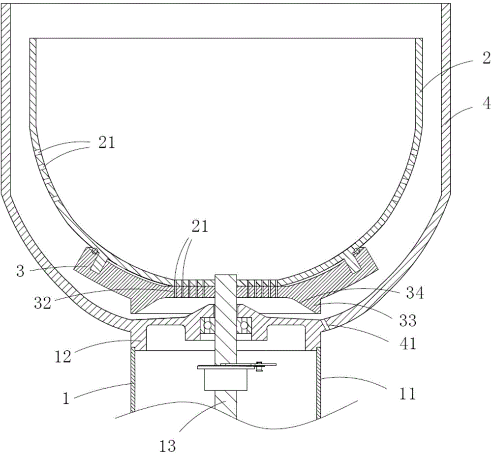
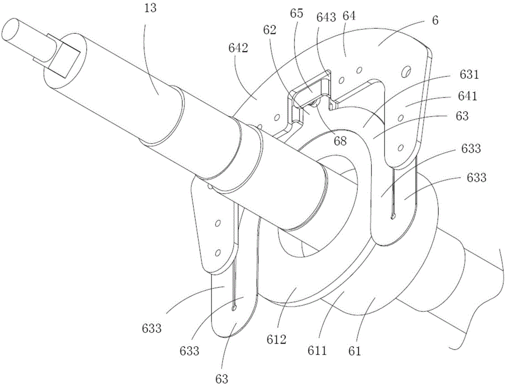
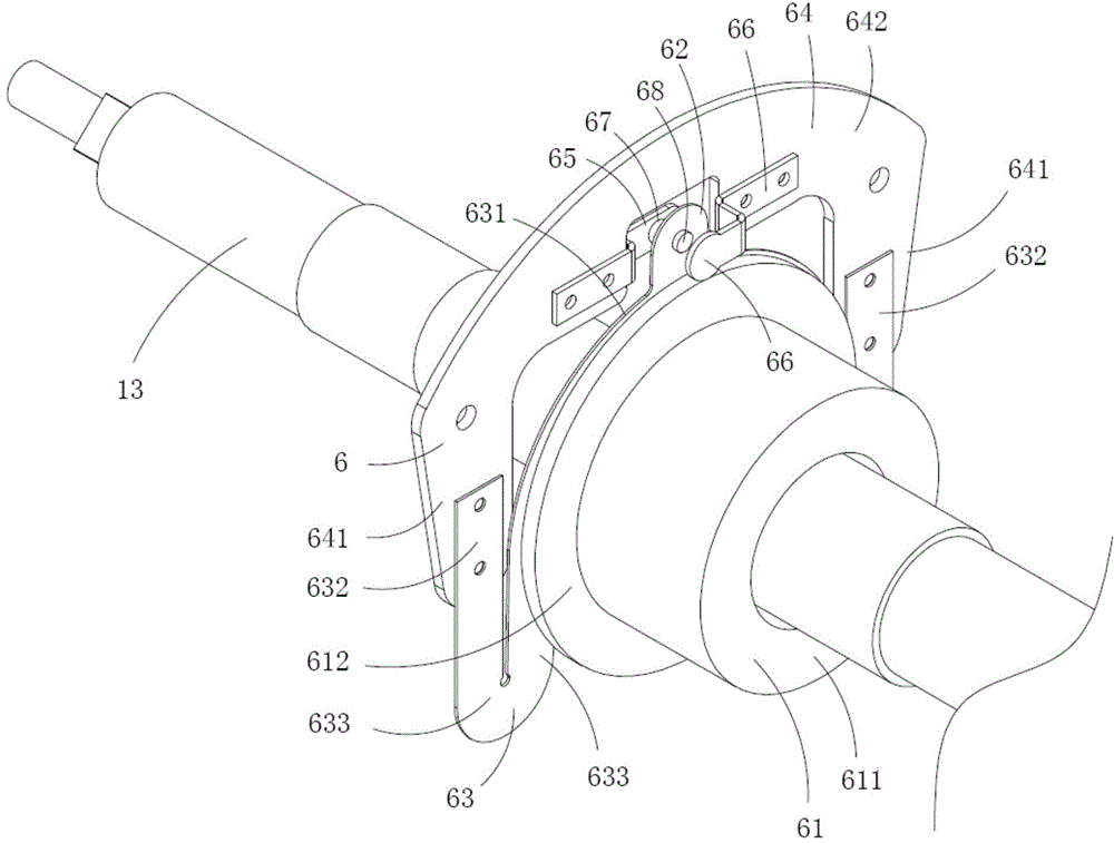
[0022] Figure 1 to Figure 7 A first embodiment of the invention is shown. in figure 1 It is a structural schematic diagram of a centrifugal filter adopting the centrifugal switch device of the present invention; figure 2 for figure 1 A schematic diagram of a three-dimensional structure when the rotating shaft of the centrifugal filter and the centrifugal switch device are used together; image 3 for figure 2 A schematic diagram of the three-dimensional structure of the rotating shaft and the centrifugal switch device when viewed from another angle; Figure 4 for figure 1 A schematic diagram of a three-dimensional structure of the centrifugal switch device in the centrifugal filter shown; Figure 5 for Figure 4 A schematic diagram of a three-dimensional structure of the centrifugal switch device shown after removing the centrifugal slider; Figure 6 for Figure 4 A schematic diagram of a three-dimensional structure of the insulating fixing plate in the centrifugal ...


PUM


Abstract

The invention discloses an insulation fixing plate of a centrifugal switch device. The insulation fixing plate is provided with a first stationary contact and a second stationary contact, is basically U-shaped, and comprises two connecting areas and a base area, wherein the two connecting areas are positioned on two sides of a rotary shaft respectively; the base area is positioned between the two connecting areas and is used for arranging the first stationary contact and the second stationary contact; a gap which is used for being arranged by directly facing the moving contact is formed in the insulating fixing plate; the first stationary contact and the second stationary contact are basically step-shaped and are arranged at the positions, on two sides of the gap, on a plate body of the insulation fixing plate; each of the first stationary contact and the second stationary contact is provided with a stationary contact point. The centrifugal switch is more reasonable and simpler in structure, a conventional spring connecting reset mode is replaced with an elastic sheet connecting reset mode, the parts are less, and fault sources are less accordingly; the working performance is more stable and more reliable.

Description

[0001] This application is a divisional application of the invention patent application with the application number 201210572433.5 and the application date is December 25, 2012, and the invention name is "centrifugal filter". technical field [0002] The invention belongs to the technical field of dehydration, and in particular relates to a part of a centrifugal switch device of a centrifugal filter. Background technique [0003] The centrifugal switch structure of the traditional centrifugal filter adopts the spring connection reset type, which has many components and many fault sources, and the working performance is not stable and reliable enough. Contents of the invention [0004] The object of the present invention is to provide a centrifugal switchgear part of a centrifugal filter with less components, less fault sources and stable and reliable working performance. [0005] The technical solution for realizing the purpose of the present invention is: the insulating ...

Claims


Application Information

Patent Timeline
Patent Type & Authority Applications(China)
IPC IPC(8): B04B7/00H01H35/10
Inventor 刘仁山
Owner SUZHOU BEITENGTE ELECTRONICS TECH
Why Eureka
Try Eureka