Filtering element cylinder locking tool

A filter cartridge and tool technology, applied in the field of filter cartridge locking tools, can solve the problems of labor, limited space, inconvenient operation, etc., and achieve the effects of simple structure, convenient locking, and overcoming limited space.

Inactive Publication Date: 2015-03-11
CHONGQING EVER YOUNG ENTERPRISES DEV
View PDF10 Cites 0 Cited by
  • Summary
  • Abstract
  • Description
  • Claims
  • Application Information

AI Technical Summary

Problems solved by technology

[0003] The biggest defect of the above-mentioned locking method is: if the distance between multiple filter cylinders is relatively close, then the space is relatively limited. Tight, there are also defects of inconvenient and laborious operation, so it is urgent to solve the above technical problems

Method used


Image

  • Filtering element cylinder locking tool
  • Filtering element cylinder locking tool
  • Filtering element cylinder locking tool

Examples


Embodiment Construction

[0015] Below in conjunction with accompanying drawing and embodiment the present invention will be further described:

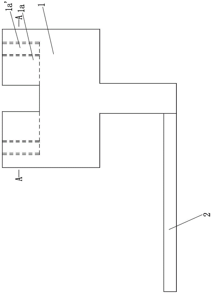
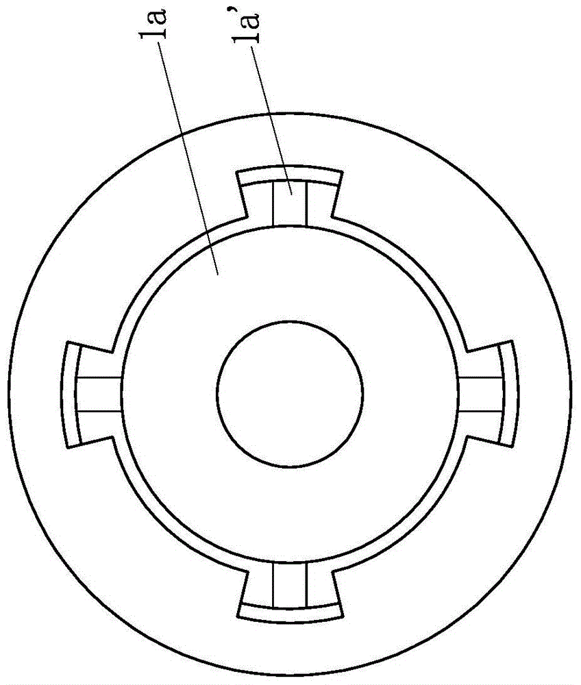
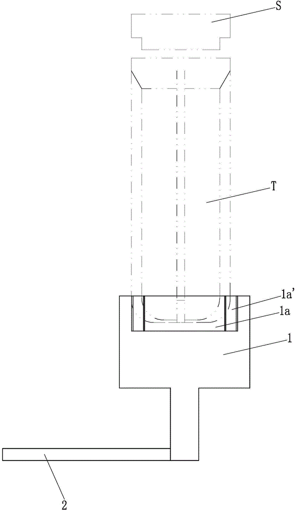
[0016] Such as figure 1 , 2 And shown in 3, a kind of filter cylinder body locking tool, this locking tool is made of tool body 1 and rotating rod 2. Among them, the tool body 1 is a two-stage stepped shaft structure with a large upper part and a smaller lower part. A rotating rod 2 is fixed on the bottom surface of the small diameter part, and the rotating rod 2 is perpendicular to the axis line of the tool body 1. Moreover, the rotating rod The distance from the top surface of 2 to the top surface of the tool body 1 is 7-10mm, and can be further preferably 8, 9, 10mm, and the length of the rotating rod 2 is 8-15mm, and can be adjusted at 9, 10, 11mm according to actual needs. , 12, 13 and 14mm are preferred. In addition, the tool body 1 and the rotating rod 2 are integrally formed by injection molding. Of course, the two can also be selected as metal par...


PUM


Abstract

The invention discloses a filtering element cylinder locking tool. A tool body is of a two-section type step shaft structure which is provided with a large upper part and a small lower part, a rotary rod is fixedly arranged at the bottom surface of the small-diameter section, and is vertical to the axis of the tool body, the distance between the top surface of the rotary rod and the top surface of the tool body is 7-10mm, the length of the rotary rod is 8-15mm, a circular groove is formed in the center of the top surface of the large-diameter section of the tool body, two to five limiting pits are uniformly formed in the groove wall of the circular groove along the circumferential direction, and the depth of each limiting pit is equal to the depth of the circular groove. The filtering element cylinder locking tool has the advantages that in the using process, the circular groove of the tool body sleeves the bottom part of a filtering element cylinder, and the limiting pits in the groove wall of the circular groove are tightly combined with reinforcing ribs on the outer wall of the filtering element cylinder; the distance between the top surface of the rotary rod and the top surface of the tool body is 7-10mm, the length of the rotary rod is 8-15mm, so that sufficient space is provided to rotate the rotary rod, and then the filtering element cylinder is locked, so as to effectively overcome the defect that the filtering element cylinder cannot be locked because of the limited space in the traditional method.

Description

technical field [0001] The invention belongs to the field of installing filter element cylinders, and in particular relates to a filter element cylinder locking tool. Background technique [0002] After the filter element is installed into the filter element cylinder, the filter element cylinder and the upper cover need to be locked together. At present, a belt or a plastic wrench is usually set in the middle of the filter cylinder. The belt or plastic wrench is in close contact with the reinforcement ribs outside the filter cylinder, and then the filter cylinder is rotated by rotating the belt or plastic wrench, so that the filter cylinder The body and the upper cover are locked. [0003] The biggest defect of the above-mentioned locking method is: if the distance between multiple filter cylinders is relatively close, then the space is relatively limited. Tight, also there is the defective of inconvenient operation, laborious, be badly in need of solving above-mentioned t...

Claims


Application Information

Patent Timeline
Patent Type & Authority Applications(China)
IPC IPC(8): B25B27/14
CPCB25B27/14
Inventor 林莹陈
Owner CHONGQING EVER YOUNG ENTERPRISES DEV
Why Eureka
Try Eureka