Lifting cab and tunnel boring machine

A tunnel boring machine and cab technology, applied in the field of construction machinery, can solve the problems of large installation distance of components, unfavorable control cost, inconvenient maintenance, etc., and achieve the effect of reducing equipment cost, lowering lifting height, and facilitating maintenance

Active Publication Date: 2015-03-11
SANY HEAVY EQUIP
View PDF9 Cites 0 Cited by
  • Summary
  • Abstract
  • Description
  • Claims
  • Application Information

AI Technical Summary

Problems solved by technology

Although this method realizes the lifting function of the cab, the practicability needs to be improved. The specific performance is as follows: firstly, considering the influence of the installation height of the oil cylinder itself, the installation distance

Method used


Image

  • Lifting cab and tunnel boring machine
  • Lifting cab and tunnel boring machine
  • Lifting cab and tunnel boring machine

Examples


Embodiment Construction

[0028] It should be noted that, in the case of no conflict, the embodiments of the present invention and the features in the embodiments can be combined with each other. Various preferred embodiments of the present invention will be further described below in conjunction with the accompanying drawings.

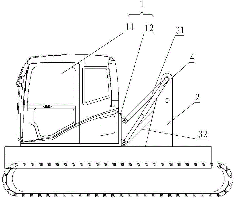
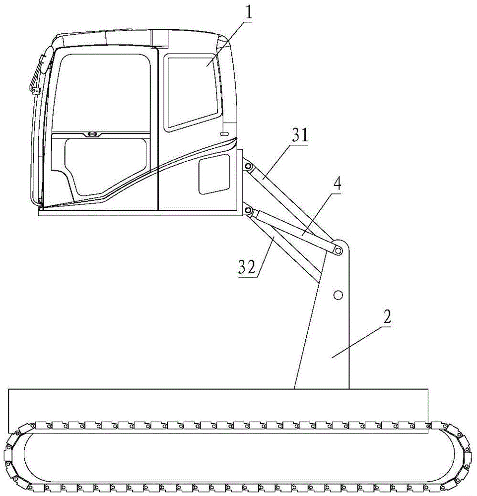
[0029] See figure 2 and image 3 , which shows the structure of the lifting cab provided by the embodiment of the present invention. The elevating cab provided in this embodiment is used for tunnel boring machines, and the elevating cab includes:

[0030] Cab 1;

[0031] The fixed bracket 2 is fixedly arranged at the rear of the cab 1; the rear mentioned in this application is the orientation close to the back of the cab 1;

[0032] The connecting rod assembly at least comprises a first connecting rod 31 and a second connecting rod 32 arranged in parallel, and the first ends of the first connecting rod 31 and the second connecting rod 32 are connected with the cab 1; the ...


PUM


Abstract

The invention discloses a lifting cab and a tunnel boring machine. The lifting cab comprises a cab, a fixed bracket, a connecting rod assembly and a driving mechanism, wherein the fixed bracket is fixedly arranged behind the cab; the connecting rod assembly at least comprises a first connecting rod and a second connecting rod which are arranged in parallel; first ends of both the first connecting rod and the second connecting rod are connected with the cab; second ends of both the first connecting rod and the second connecting rod are hinged with the fixed bracket; the driving mechanism is used for driving the connecting rod assembly to rotate along the vertical face. According to the lifting cab provided by the invention, a lifting device is arranged behind the cab, so that the space in the horizontal direction is effectively utilized, the mounting height of the complete machine in the vertical direction is reduced when the effective lifting height is ensured, and the lifting cab is beneficial for ensuring balance of the gravity center of the complete machine; the number of required driving parts is small, which is beneficial for reducing equipment cost; moreover, the lifting device is arranged behind the cab, so that the lifting cab also has the advantage of convenience for repair.

Description

technical field [0001] The invention relates to the field of engineering machinery, in particular to a lifting cab and a tunnel boring machine. Background technique [0002] Tunnel boring machine is a kind of important construction machinery, and its application is very extensive. Existing tunnel boring machines mainly include a traveling mechanism, a cab arranged on the traveling mechanism, and a cutting part arranged at the front end of the cab. Among them, the cab is fixed on the chassis of the traveling mechanism, so that the operator can explore the working conditions ahead. However, for some complex work transfers, such as a large tunnel section, if the fixed height of the cab is low, it is inevitable that the driver's line of sight will be blocked, which is not good for the operator's work; if the fixed height of the cab is high, it will As a result, the center of gravity of the equipment moves upward, which has a certain impact on the stability of the whole machine...

Claims


Application Information

Patent Timeline
IPC IPC(8): B62D33/063
CPCB62D33/0636
Inventor 姜海涛牛建强张春政
Owner SANY HEAVY EQUIP
Why Eureka
Try Eureka