Pilot control valve

A pilot control valve and spool technology, applied in fluid pressure actuators, servo motor components, mechanical equipment, etc., can solve the problems of difficult pressure adjustment, slow adjustment speed, and inability to adjust the pressure of the thread of the adjustment rod to achieve full pressure Continuously adjustable, rapid pressure adjustment, small space occupation effect

Inactive Publication Date: 2015-03-11
SHANGHAI LIXIN HYDRAULIC
View PDF14 Cites 0 Cited by
  • Summary
  • Abstract
  • Description
  • Claims
  • Application Information

AI Technical Summary

Problems solved by technology

Most of the existing pressure regulating valve adjustment methods are screw adjustment. When the system pressure is high, the adjustment torque will increase accordingly, and it is difficult to adjust the pressure. Some need to use tools such as wrenches to adjust circles. When the thread of the rod is damaged, the pressure cannot be adjusted, and it is difficult to realize the continuous adjustment of the pressure in the whole range by the rotation of the thread.

Method used


Image

  • Pilot control valve
  • Pilot control valve
  • Pilot control valve

Examples


Embodiment Construction

[0021] The preferred embodiments of the present invention are given below in conjunction with the accompanying drawings to describe the technical solution of the present invention in detail.

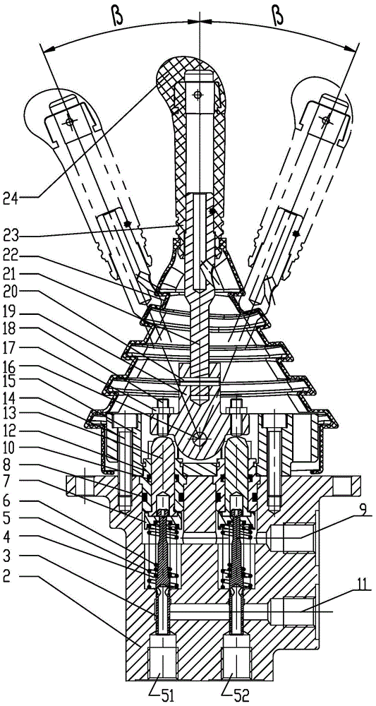
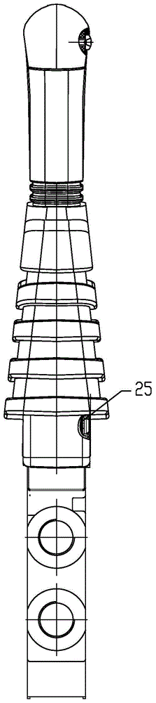
[0022] Such as figure 1 and figure 2 As shown, a pilot control valve includes a valve body 2, a valve core 3, and a handle rod 21, such as Figure 5 As shown, the valve body 2 has two stepped main valve holes 41, an oil inlet P11 and an oil outlet T9, both the oil inlet P11 and the oil outlet T9 communicate with the two main valve holes 41, and the two The lower end of the main valve hole communicates with the first working oil port 51 and the second working oil port 52 respectively.

[0023] A spool 3, a control spring 6, a spring seat 7, a push rod 13, and a push rod sleeve 12 are installed in each main valve hole 41. The head of the spool 3 is inserted into the spring seat 7, and the control spring 6 is installed on the spring seat 7. Between the valve core 3 , the upper end of th...


PUM


Abstract

The invention relates to a pilot control valve. The pilot control valve comprises a valve body, a valve core and a handle rod, two ladder type main valve holes, an oil inlet P and an oil outlet T are opened in the valve body, the oil inlet P and oil outlet T are communicated with the two main valve holes, the lower end of one main valve hole is communicated with a first working oil hole, and the lower end of the other main valve hole is communicated with a second working oil hole. According to the pilot control valve, the pressure is regulated through operating the handle rod; the pilot control valve is small in space usage, light, convenient and easy to operate, and quick, precise and easy to regulate pressure, and meanwhile, the same valve is provided with two working oil holes to respectively control the pressure of two oil passages, and the pressure is continuously adjustable in the whole process.

Description

technical field [0001] The invention relates to a control valve, in particular to a pilot control valve with convenient operation, fast, accurate and stable pressure regulation, and continuous pressure regulation in a full range. Background technique [0002] Pressure regulating valves are often used in hydraulic systems to control the system pressure. Most of the existing pressure regulating valve adjustment methods are thread adjustment. When the system pressure is high, the adjustment torque will increase accordingly, making it difficult to adjust the pressure. When the thread of the rod is damaged, the pressure cannot be adjusted, and it is difficult to realize the continuous adjustment of the pressure in the whole range by the rotation of the thread. Therefore, it is very necessary to need a pressure regulating valve that is easy to operate, fast, accurate and stable in pressure regulation, and can realize continuous pressure regulation in a full range. Contents of t...

Claims


Application Information

Patent Timeline
Patent Type & Authority Applications(China)
IPC IPC(8): F15B13/02
CPCF15B13/02
Inventor 姚志伟翟俊华徐晋易何俊
Owner SHANGHAI LIXIN HYDRAULIC
Why Eureka
Try Eureka