
Protective components for electric heating pipes for air conditioners

An electric heating tube and air-conditioning technology, which is applied in household heating, household heating, heating methods, etc., can solve the problems of high-temperature combustion, falling or falling off of air-conditioning machines, fire accidents, etc., to achieve extended service life, low cost, The effect of preventing ignition

Active Publication Date: 2017-03-15
SUZHOU SUTENG ELECTRONICS TECH
View PDF4 Cites 0 Cited by
  • Summary
  • Abstract
  • Description
  • Claims
  • Application Information

AI Technical Summary

Problems solved by technology

[0003] However, during long-term use, the electric heating element, that is, the electric heating wire, is more likely to be carbonized at the welding point between it and the lead-out rod, so a large amount of heat will be accumulated during use, which will cause the welding point between the lead-out rod and the electric heating wire to fuse ; The fusing process continues to be in a high temperature state. The cold area of ​​the electric heating tube corresponding to the lead-out rod and the heating area corresponding to the electric heating wire continue to be high temperature at the junction of the two, resulting in a gap between the cold area of ​​the electric heating tube and the heating area. There is a large area of ​​fusing parts at the junction, and as a result, the fusing parts will continue to fall or fall off. After the falling parts come into contact with other parts in the air conditioner (such as plastic panels, wiring harnesses, etc.), it is easy to directly cause high-temperature combustion of the entire air conditioner. It may even lead to serious fire accidents

Method used


Image

  • Protective components for electric heating pipes for air conditioners
  • Protective components for electric heating pipes for air conditioners
  • Protective components for electric heating pipes for air conditioners

Examples


Embodiment Construction

[0025] Below in conjunction with accompanying drawing of description, the present invention will be further described.

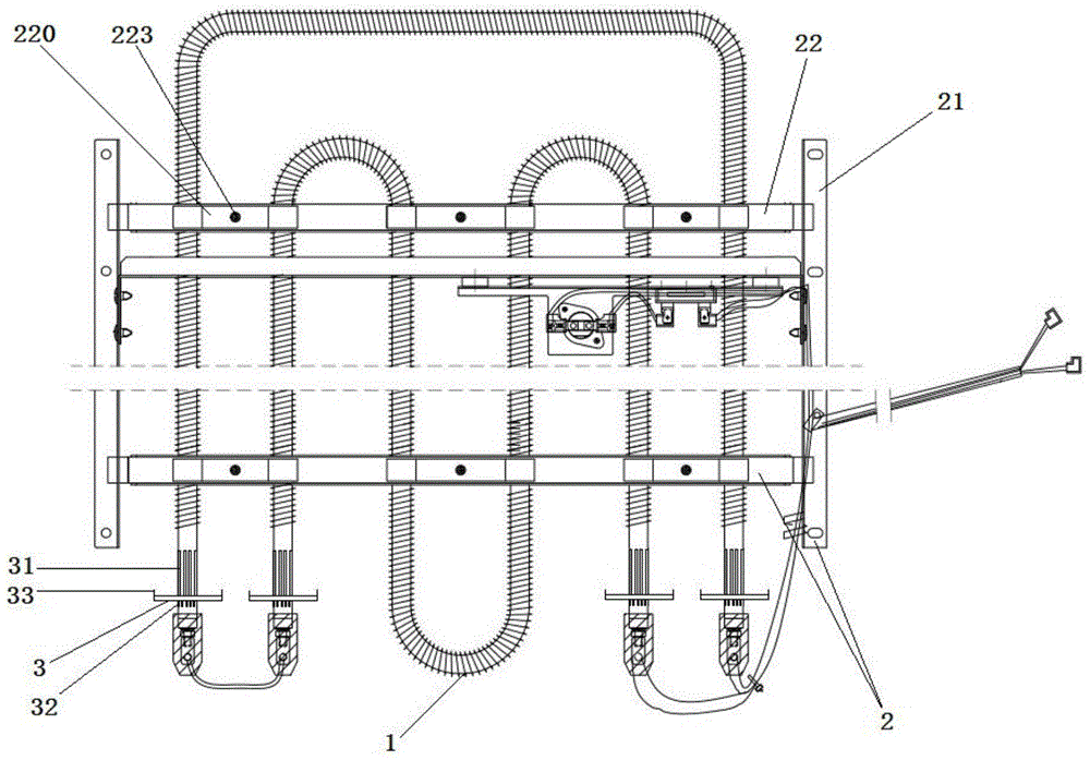
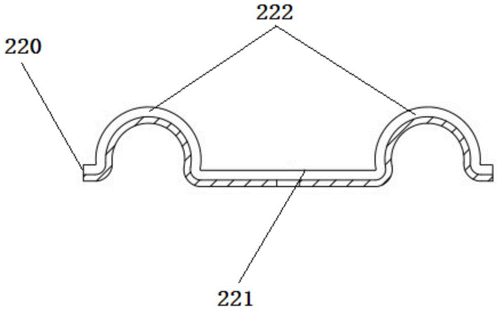
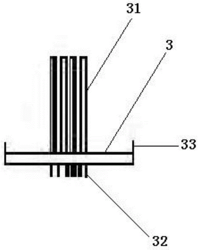
[0026] Such as figure 1 , figure 2 and image 3 As shown, an electric heating tube protection component for air conditioning includes an electric heating tube frame 2 for fixing the electric heating tube 1, and also includes a set of disks for the tube body at the cold zone at the end of the electric heating tube 1 3. The sleeve 3 is used to receive the fragments that fall off from the fusing part of the electric heating tube 1 above the sleeve 3 due to high temperature; The size is matched, the plane of the sleeve 3 is perpendicular to the axial direction of the pipe body in the cold zone; the inner ring edge of the sleeve 3 is provided with grid bars extending upward and clamping the end pipe body of the electric heating tube 1 31. The grid strips 31 extend all the way to the junction of the cold area and the heating area at the end of the electric hea...


PUM


Abstract

The invention discloses a protective member for an electric heating pipe of an air conditioner. The protective member comprises an electric heating pipe frame body for fixing an electric heating pipe, and a sleeve tray arranged on a cold region position pipe body at the tail end of the electric heating pipe in a sleeving manner, wherein the sleeve tray is used for carrying fragments falling from an electric heating pipe fusing position above the sleeve tray due to high temperature; the hollow inner ring size of the sleeve tray is matched with the pipe diameter size of the cold region position pipe body; the plane of the sleeve tray is vertical to the axial direction of the cold region position pipe body; the inner ring edge of the sleeve tray is provided with grid strips which extend upwards and clamp the tail end pipe body of the electric heating pipe; the grid strips extend to the junction of the tail end cold region and the heating region of the electric heating pipe all the way. The protective member has the advantages of simple structure, convenience in manufacturing, safety, reliability, high generality, low cost and long service life; the fragments falling from the high-temperature fusing position can be collected, so that ignition of the fallen fragments is avoided; the junction of the cold region and the heating region of the electric heating pipe can be still kept in a fixed state without falling after fusing.

Description

technical field [0001] The invention relates to a matching component of an electric heating pipe, in particular to a protective component for an electric heating pipe used in an air conditioner. Background technique [0002] Along with the raising of people's living conditions, the use of air conditioner is more and more extensive. At present, the electric heating tube for air conditioners is a general electric heating element, specifically the electric heating wire arranged in the pipe fitting, which is connected to the lead-out rod in the pipe fitting by welding, and the end of the lead-out rod extends out of the pipe body and is welded to the terminal piece, and then The terminal strips are connected to the wire set. [0003] However, during long-term use, the electric heating element, that is, the heating wire, is more prone to carbonization at the welding point between it and the lead-out rod, so a large amount of heat will accumulate during use, which will cause the w...

Claims


Application Information

Patent Timeline
Patent Type & Authority Patents(China)
IPC IPC(8): F24F13/00
CPCF24F13/00
Inventor 周天毫
Owner SUZHOU SUTENG ELECTRONICS TECH
Learn More