Reverberation room platform based method for testing electromagnetic environment effects of electronic system

An electronic system and electromagnetic environment technology, applied in the measurement of electricity, measurement of electrical variables, measurement devices, etc., can solve the problems of inability to accurately guide the safety of electronic systems, inability to ensure the threshold value of electromagnetic environmental effects of test values, and unclear physical meaning. Achieve the effect of clear physical meaning, easy promotion and quick installation

Active Publication Date: 2015-03-11
PEOPLES LIBERATION ARMY ORDNANCE ENG COLLEGE
View PDF5 Cites 21 Cited by
  • Summary
  • Abstract
  • Description
  • Claims
  • Application Information

AI Technical Summary

Problems solved by technology

But this is not in line with the actual situation, because the electromagnetic environmental effect threshold of the electronic system in the reverberation room environment should be the electric field strength in the reverberation room when the electronic system can cause the effect under the minimum forward input power. The above method is directly from Considering the problem from the perspective of electric field strength, the physical meaning is not clear, and there are obvious unreasonable points. It cannot be guaranteed that the test value is the real threshold value of the electromagnetic environment effect of the electronic system, which leads to the inability of the test results to accurately guide the electronic system in the actual electromagnetic environment. safe to use

Method used


Image

  • Reverberation room platform based method for testing electromagnetic environment effects of electronic system
  • Reverberation room platform based method for testing electromagnetic environment effects of electronic system
  • Reverberation room platform based method for testing electromagnetic environment effects of electronic system

Examples


Embodiment Construction

[0022] In order to make the technical problems to be solved in the present invention, technical solutions and beneficial effects clearer, the following will be combined with the attached figure 1 and specific embodiments are described in detail.

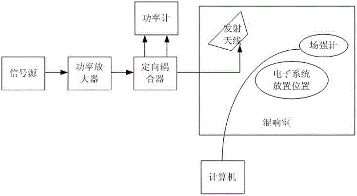
[0023] Refer to attached figure 1 , the test platform of this embodiment 1 is shown in the figure, and the test platform includes: a reverberation chamber, a signal source, a power amplifier, a directional coupler, a power meter, a transmitting antenna and a field strength meter.

[0024] Step 1. Build a test platform:

[0025] Place the electronic system to be tested and the field strength meter inside the working area in the reverberation chamber, and the field strength meter is connected to the computer outside the reverberation chamber through an optical fiber; set the signal source, power amplifier, directional coupler and power meter outside the reverberation chamber , the output end of the signal source is connected to the i...


PUM


Abstract

The invention discloses a reverberation room platform based method for testing electromagnetic environment effects of an electronic system. The method is applicable to threshold testing of the electromagnetic environment effects of the electronic system on the basis of a reverberation room platform. The method includes the steps: 1, setting up a test platform; 2, keeping a reside position of a stirrer unchanged, setting a signal source transmitting frequency, increasing amplification factor of a power amplifier until electromagnetic environment effects occur in the electronic system, and recording the current forward input power; 3, changing the reside position of the stirrer, and repeating the step 2; 4, repeating the step 3 to obtain forward input powers corresponding to a plurality of reside positions of the stirrer; 5, taking the minimal forward input power obtained at the step 4 as the input power of a transmitting antenna, enabling the stirrer to rotate by one circle step by step to obtain corresponding electric field strength at each reside position, and taking the maximum value of the electric field strength as the threshold of the electromagnetic environment effects of the electronic system under the signal source transmitting frequency. The reverberation room platform based method has the advantages of procedure simplicity, easiness in implementation and high repeatability of test results.

Description

technical field [0001] The invention relates to an electronic system electromagnetic environment effect test method based on a reverberation chamber platform, and is especially suitable for the electronic system electromagnetic environment effect threshold test method based on a reverberation chamber platform. Background technique [0002] With the rapid development of science and technology, microelectronics technology has been widely used in electronic systems, making the equipment more and more electronic and integrated, with more and more powerful functions, and at the same time, it is more and more susceptible to the influence of the electromagnetic environment. Electronic systems often work in complex electromagnetic environments, such as weapons and equipment, industrial control instrument rooms, transportation vehicles and other fields, as well as instrument cabins of large equipment, passenger cabins and spacecraft cabins, working cabins, and multiple-input multiple-...

Claims


Application Information

Patent Timeline
Patent Type & Authority Applications(China)
IPC IPC(8): G01R31/00
Inventor 陈亚洲王庆国程二威周星曲兆明田庆民
Owner PEOPLES LIBERATION ARMY ORDNANCE ENG COLLEGE
Why Eureka
Try Eureka