Holographic display device with sight tracking function

A holographic display and line-of-sight tracking technology, which is applied to projection devices, printing devices, color TV components, etc., can solve the problems of increasing system weight, not being able to block each other, increasing system complexity, etc. simple effect

Inactive Publication Date: 2015-03-11
SOUTHEAST UNIV
View PDF5 Cites 29 Cited by
  • Summary
  • Abstract
  • Description
  • Claims
  • Application Information

AI Technical Summary

Problems solved by technology

The added infrared light source and infrared camera can be independent components, which will increase the complexity of the whole system. For example, the infrared camera needs an optical lens to complete the focusing, and this focusing l...

Method used


Image

  • Holographic display device with sight tracking function
  • Holographic display device with sight tracking function

Examples


Embodiment Construction

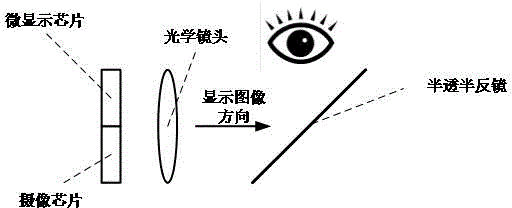
[0020] figure 1 Shown is the preferred structure schematic diagram of the present invention. Among the figure, the micro-display chip and the imaging chip are located on the same plane. In the present invention, the micro-display chip is preferably an LCoS chip (liquid crystal on silicon micro-display chip, and LCoS is a reflective micro-display chip, which requires an additional light source to irradiate the display screen, and utilizes reflected light display, simplified and not drawn in the figure), the camera chip is a CMOS photosensitive chip, the microdisplay chip and the camera chip can be two independent chips on the same substrate, or on the same chip, for example, on the same The LCoS chip area and the CMOS photosensitive chip area are prepared on the silicon wafer, or the CMOS photosensitive area and the LCoS area are fused together, that is, the CMOS photosensitive pixel unit is prepared in the gap between the LCoS pixel unit, so that the same chip can have both s...


PUM


Abstract

The invention discloses a holographic display device with a sight tracking function. The holographic display device is composed of a micro-display chip, a camera chip, an optical camera and an optical imaging system; the display chip and the camera chip share the optical camera and the optical imaging system; the optical camera and the optical imaging system are used for imaging human eyes' images on the camera chip; the micro-display chip displays dynamic holographic images. A scheme of sharing an optical path by a micro-display system and a human eyes' sight tracking system is provided; with adoption of the sharing of the optical path, the integration and reliability of the system can be improved, the volume of the system is reduced and the low weight of the system is realized.

Description

technical field [0001] The present invention relates to a holographic display device, in particular to a holographic display device with a line of sight tracking function. Background technique [0002] Wearable microdisplay systems can be used in application scenarios such as virtual reality display and augmented reality display. Representative products include Sony's helmet display device, Oclulus' virtual reality display helmet, and Google's smart glasses. At present, wearable micro-display systems mainly use micro-display chips as the image display source, such as LCoS, OLED on Silicon, etc., and through the optical imaging system, the human eye can see a magnified virtual image. This display method, for the monocular optical system, always displays a two-dimensional virtual enlarged image at a fixed position in front of the eye, so it can only display two-dimensional plane images, and the displayed image screen does not have three-dimensional space. depth of field. One...

Claims


Application Information

Patent Timeline
IPC IPC(8): G02B27/01G03B29/00G03H1/22H04N5/225
CPCG02B27/0103G02B2027/0109G03B29/00G03H1/22
Inventor 夏军
Owner SOUTHEAST UNIV
Why Eureka
Try Eureka