Blanking circuit of encoder of 1/4-scanning LED display screen

A technology of LED display screen and blanking circuit, applied in static indicators, instruments, etc., can solve the problems of complex structure and difficult control of blanking circuit, and achieve the effect of simple structure, solving smear, and simple wiring.

Inactive Publication Date: 2015-03-11
LICERAM ELECTRONICS TECH
View PDF6 Cites 0 Cited by
  • Summary
  • Abstract
  • Description
  • Claims
  • Application Information

AI Technical Summary

Problems solved by technology

[0008] The technical problem to be solved by the present invention is to provide a blanking circuit for a quarter-scan LED display screen decoder, which solves the problem that the structure of the blanking circuit in the prior art is complex and difficult to control

Method used


Image

  • Blanking circuit of encoder of 1/4-scanning LED display screen

Examples


specific Embodiment 1

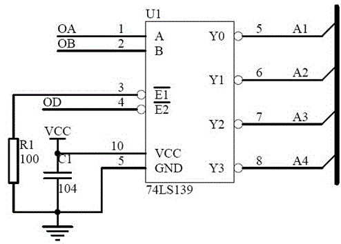
[0034] A blanking circuit for a quarter-scan LED display screen decoder, including a decoder U1, a resistor R1, and a capacitor C1, and the decoder U1 includes a power supply terminal VCC, a ground terminal GND, and a first control terminal A, the second control terminal B, the first enable terminal E1, the second enable terminal E2, the first to fourth output terminals, the capacitor C1 is connected between the power supply terminal VCC and the ground terminal GND, the first control terminal A It is connected with the external input signal OA, the second control terminal B is connected with the external input signal OB; the first enable terminal E1 is connected with one end of the resistor R1, the other end of the resistor R1 is grounded, and the second enable terminal E2 is connected with the external switch signal OD connection; the first output terminal Y0 is connected to the first row and the fifth row of the LED display module, the second output terminal Y1 is connected t...

specific Embodiment 2

[0040] A blanking circuit for a quarter-scan LED display screen decoder, including a decoder U1, a resistor R1, and a capacitor C1, and the decoder U1 includes a power supply terminal VCC, a ground terminal GND, and a first control terminal A, the second control terminal B, the first enable terminal E1, the second enable terminal E2, the first to fourth output terminals, the capacitor C1 is connected between the power supply terminal VCC and the ground terminal GND, the first control terminal A It is connected with the external input signal OA, the second control terminal B is connected with the external input signal OB; the first enable terminal E1 is connected with one end of the resistor R1, the other end of the resistor R1 is grounded, and the second enable terminal E2 is connected with the external switch signal OD Connection; the first output terminal Y0 is connected to the 1st, 5th and 9th rows of the LED display module, and the second output terminal Y1 is connected to ...

specific Embodiment 3

[0046]A blanking circuit for a quarter-scan LED display screen decoder, including a decoder U1, a resistor R1, and a capacitor C1, and the decoder U1 includes a power supply terminal VCC, a ground terminal GND, and a first control terminal A, the second control terminal B, the first enable terminal E1, the second enable terminal E2, the first to fourth output terminals, the capacitor C1 is connected between the power supply terminal VCC and the ground terminal GND, the first control terminal A It is connected with the external input signal OA, the second control terminal B is connected with the external input signal OB; the first enable terminal E1 is connected with one end of the resistor R1, the other end of the resistor R1 is grounded, and the second enable terminal E2 is connected with the external switch signal OD Connection; the first output terminal Y0 is connected to the 1st, 5th and 9th rows of the LED display module, and the second output terminal Y1 is connected to t...


PUM


Abstract

The invention discloses a blanking circuit of an encoder of 1/4-scanning LED display screen. The blanking circuit comprises the encoder, a resistor and a capacitor. The encoder comprises a power source end, a ground end, a first control end, a second control end, a first enable end, a second enable end and first to fourth output ends, wherein the capacitor is connected between the power source end and the ground end, the first control end and the second control end are connected with two channels of control signals externally inputted respectively, the first enable end is connected with one end of the resistor, the other end of the resistor is grounded, and the second enable end is in signal connection with external switch signals; each output end is connected with an independent LED wire. By the blanking circuit of the encoder, blanking is controlled by controlling duty ratio of the external switch signals, and the problem of image tails of the LED display screen is effectively solved. Meanwhile, the blanking circuit is simple in structure, cost is saved and wiring is facilitated.

Description

technical field [0001] The invention belongs to the application field of electronic products, and in particular relates to a blanking circuit for a quarter-scan LED display screen decoder. Background technique [0002] A phenomenon that has always existed in the LED display industry is smearing and caterpillars. Major controller manufacturers continue to improve this phenomenon. Smearing will appear before and after smearing. It will cause a problem of section capacitor itself, and it will also act as a capacitor, which is the front blanking; the so-called rear smear: that is, the line tube 4953 double P-channel-MOS tube, when working, there is a 5V to 0V switch on and off, In the process of reducing the voltage, there will be a dark and bright smear of the forward voltage drop of the LED in the (N-1) row. [0003] The control signals provided by different controllers are different. Most of the above solutions are not compatible with all controllers. The finished PCB board ...

Claims


Application Information

Patent Timeline
Patent Type & Authority Applications(China)
IPC IPC(8): G09G3/32
Inventor 孙道明司马云吴会利谢中明
Owner LICERAM ELECTRONICS TECH
Why Eureka
Try Eureka