Ion implanter scanning device and scanning method

A technology of ion implanter and scanning device, which is applied in the direction of discharge tubes, electrical components, circuits, etc., can solve the problems of implantation angle and setting implantation angle deviation, and achieve the effects of simplified mechanism, simplified motion realization mode, and obvious cost advantages

Inactive Publication Date: 2015-03-11
48TH RES INST OF CHINA ELECTRONICS TECH GROUP CORP
View PDF5 Cites 15 Cited by
  • Summary
  • Abstract
  • Description
  • Claims
  • Application Information

AI Technical Summary

Problems solved by technology

[0005] However, the existing scanning device can basically only realize the mechanical scanning in the vertical direction and the adjustment of the tilt angle of the wafer. In fact, it is generally difficult for the parallel ion beams reaching the wafer on the target stage to reach the ideal state of being perpendicular to the wafer, although it is possible There is only a deviation of about 1 to 3 degrees, but it will still cause a deviation between the actual injection angle and the set injection angle, which is still unacceptable for some processes

Method used


Image

  • Ion implanter scanning device and scanning method
  • Ion implanter scanning device and scanning method
  • Ion implanter scanning device and scanning method

Examples


Embodiment Construction

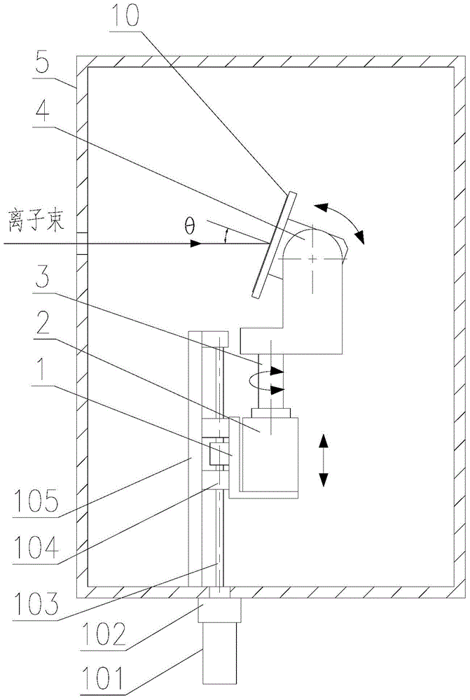
[0039] A scanning device for an ion implanter such as figure 1 As shown, it mainly includes a vertical scanning mechanism 1, a horizontal rotating mechanism 2, a scanning axis 3 and a target platform 4. Further, the vertical scanning mechanism 1 of the scanning device mainly includes a driving motor 101, a rotary seal 102, a screw pair 103, linear guide rail 104 and fixed seat 105. The drive motor 101 and the rotary seal 102 of the vertical scanning mechanism 1 are placed outside the vacuum chamber 5 , and the rest are all placed inside the vacuum chamber 5 . The inside of the vacuum chamber 5 is a sealed high vacuum environment required by the ion implantation process.

[0040] The function of the vertical scanning mechanism 1 is to push the horizontal rotating mechanism 2 , the scanning axis 3 and the target stage 4 to perform vertical scanning movement as a whole. When the driving motor 101 rotates, the screw pair 103 converts the rotational torque into a linear thrust, a...


PUM


Abstract

The invention discloses an ion implanter scanning device and a scanning method. The scanning device comprises a fixed base, a vertical scanning mechanism which is installed on the fixed base and capable of moving up and down along the fixed base vertically, a horizontal rotation mechanism which is installed on the vertical scanning mechanism and can horizontally rotate and a scanning shaft which is installed on the horizontal rotation mechanism; the top end of the scanning shaft is provided with a target platform which can rotate along with the scanning shaft and used for clamping a wafer; an angle adjusting mechanism which adjusts the chip gradient is installed on the target platform to rectify an iron implantation angle. The scanning method comprises arranging an implantation angle theta firstly and calculating the scanning stroke s and the scanning times n; enabling the target platform 4 to rotate by an angle alpha to perform angularity correction, enabling the target platform 4 to incline to the implantation angle theta and finally aching scanning. The scanning device and method can achieve target platform vertical direction scanning movement, meanwhile can enable the target platform to rotate surrounding the scanning shaft through the horizontal rotation mechanism to perform angle correction and can achieve more accurate implantation angle control.

Description

technical field [0001] The invention relates to the technical field of semiconductor equipment, in particular to an ion implanter scanning device and a scanning method. Background technique [0002] Ion implanter is one of the key equipment in semiconductor process. In order to ensure the uniformity of the ion implantation dose, the ion implantation equipment generally needs to adopt a certain scanning mode. Due to the increasing size of silicon wafers and higher and higher requirements for ion implantation processes, it is difficult for the early batch-type target discs to meet the new process requirements, and single-chip implantation target platforms have gradually become the mainstream of current ion implanters. In this type of implanter system, the general requirement is that the ion beam undergoes electrical scanning and electromagnet correction in the horizontal direction, and finally reaches the target platform to diverge in parallel, that is, the ion beam remains s...

Claims


Application Information

Patent Timeline
Patent Type & Authority Applications(China)
IPC IPC(8): H01J37/317H01J37/02
CPCH01J37/02H01J37/023H01J37/3171
Inventor 许波涛彭立波易文杰钟新华
Owner 48TH RES INST OF CHINA ELECTRONICS TECH GROUP CORP
Why Eureka
Try Eureka