

Miniaturized electric coupler for circular network
A technology of electrical connectors and networks, which is applied in the direction of network connectors, connections, parts of connection devices, etc., can solve the problems that cannot meet the miniaturization of electronic equipment, and achieve the effect of solving large volumes
- Summary
- Abstract
- Description
- Claims
- Application Information
AI Technical Summary
Problems solved by technology
Method used
Image

Examples
Embodiment Construction
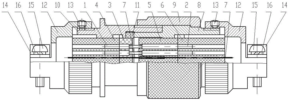
[0013] Such as figure 1 , 2 As shown, the present invention includes pin 1, jack 2, pin upper insulator 3, pin lower insulator 4, jack upper insulator 5, jack lower insulator 6, metal partition 7, plug housing 8, locking ring 9. Socket shell 10, sealing ring 11, tail cover 12, set screw 13, cable clamp 14, screw 15, washer 16.
[0014] Pin 1 and jack 2 together form a contact body, and the terminals of pin 1 and jack 2 are soldered or crimped wires.
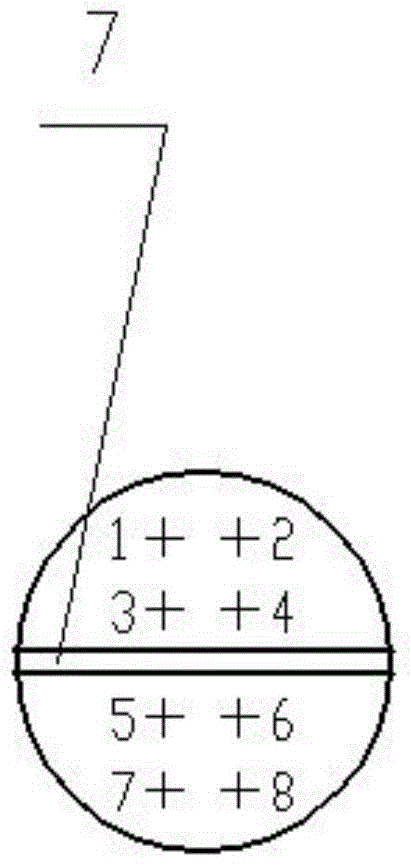
[0015] Pin 1 is put into the hole of the upper insulator 3 and the lower insulator 4 of the pin, the jack 2 is put into the hole of the upper insulator 5 of the jack and the lower insulator 6 of the jack, and several (generally 4) pins 1 Or several (generally 4) jacks 2 are separated by metal partitions 7 . There is a hole that can be welded to the ground wire on the edge of the end of the metal partition 7 .
[0016] The pin 1 and the jack 2 have cylindrical bosses, which are respectively matched with the upper insulator 3 o...
PUM
 Abstract
Description
Claims
Application Information