Automatic changeover switch controller circuit

An automatic transfer switch and controller technology, applied in program control, computer control, general control system, etc., can solve the problems of reduced reliability, damage to electrical equipment, and the controller cannot reliably select the power supply, and achieve high reliability. , the effect of simple circuit design

Inactive Publication Date: 2014-10-22
CNC ELECTRIC GRP
View PDF5 Cites 1 Cited by
  • Summary
  • Abstract
  • Description
  • Claims
  • Application Information

AI Technical Summary

Problems solved by technology

[0002] At present, the voltage detection circuit of the automatic transfer switch controller circuit generally adopts the signal processing circuit of voltage transformer step-down or optocoupler detection. Due to the large size of the voltage transformer, the cost is high, and the electrical characteristics of the optocoupler are less affected by the ambient temperature. Large, the monitoring data often cannot accurately sample the real value of the power supply, causing the automatic transfer switch controller to make a wrong judgment, resulting in the failure of the electrical equipment to operate in the normal power environment, and especially serious damage to the electrical equipment; commonly used backup conversion circuits Generally, a single relay with two normally open and two normally closed relays is used for control. When a single relay is switched on load, the switching contact of the relay is inflexible due to the arc generated during the switching period, and the reliability is reduced, which makes the controller unable to reliably select the power supply.

Method used


Image

  • Automatic changeover switch controller circuit
  • Automatic changeover switch controller circuit
  • Automatic changeover switch controller circuit

Examples


Embodiment Construction

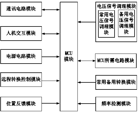
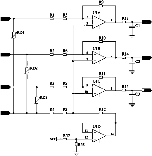
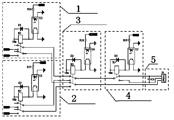
[0020] see figure 1 , is a block diagram of the first embodiment of the automatic transfer switch controller circuit of the present invention. see figure 2 ,for figure 1 The circuit schematic diagram of the commonly used voltage signal conditioning module and the standby voltage signal conditioning module. see image 3 ,for figure 1 The circuit schematic diagram of the spare conversion module commonly used in China. like figure 1 , figure 2 , image 3 As shown, the automatic transfer switch controller circuit provided in the first embodiment of the present invention at least includes an MCU module, a communication circuit module connected to the MCU module, a human-computer interaction module, a power circuit module, and a remote transfer control module, a position feedback module, a voltage signal conditioning module, a circuit module required by the MCU, a common standby conversion module, and a frequency detection module. The voltage signal conditioning module inc...


PUM


Abstract

The invention relates to an automatic changeover switch controller circuit. A voltage signal conditioning module contains a common voltage signal conditioning module and a standby voltage signal conditioning module. A common-standby conversion module contains a common power selection module, a backup power selection module, a common-backup power selection module, a common-backup conversion control module and a motor which are successively connected. A phase line A of the common voltage signal conditioning module is successively connected in series with a resistor R1, a resistor R5, an operational amplifier U1A, a resistor R13 and a capacitor C1. A resistor R9 is connected between a pin 2 and a pin 1 of the operational amplifier U1A. The other end of the capacitor C1 is grounded, and an AD converter AD1 is connected between the resistor R13 and the capacitor C1. According to the automatic changeover switch controller circuit provided by the invention, three relays are combined for use. The circuit is simply designed and has high reliability. The defect that the volume of a voltage transformer is large, cost is high and electrical characteristics of an optical coupler are highly influenced by environment temperature is solved.

Description

technical field [0001] The invention relates to the field of transfer switch controllers, more specifically, to an automatic transfer switch controller circuit. Background technique [0002] At present, the voltage detection circuit of the automatic transfer switch controller circuit generally adopts the signal processing circuit of voltage transformer step-down or optocoupler detection. Due to the large size of the voltage transformer, the cost is high, and the electrical characteristics of the optocoupler are less affected by the ambient temperature. Large, the monitoring data often cannot accurately sample the real value of the power supply, causing the automatic transfer switch controller to make a wrong judgment, resulting in the failure of the electrical equipment to operate in the normal power environment, and especially serious damage to the electrical equipment; commonly used backup conversion circuits A single relay with two normally open and two normally closed re...

Claims


Application Information

Patent Timeline
Patent Type & Authority Applications(China)
IPC IPC(8): G05B19/042
Inventor 余存泰黎永胜赵东杰彭昆明
Owner CNC ELECTRIC GRP
Why Eureka
Try Eureka