Crowned strip conveying device

A conveying device and crown tape technology, which is applied in transportation and packaging, winding strips, function indication, etc., can solve the problems of crown tape supply interruption, tire production interruption, installation trouble, etc., to maintain continuity and ensure efficiency , the effect of simple operation

Inactive Publication Date: 2015-03-18
青岛海琅智能装备有限公司
View PDF9 Cites 1 Cited by
  • Summary
  • Abstract
  • Description
  • Claims
  • Application Information

AI Technical Summary

Problems solved by technology

[0002] In the tire forming process, there is a process of winding the crown tape. The current cap tape feeding device uses the active roller to extract the crown tape from the I-shaped wheel for storing the crown tape and feed it to the next step. In the process, the cap strip feeding device is only provided with a material wheel for placing the I-shape wheel. When the cap strips on the material wheel are conveyed, it is necessary to switch the new I-shape full of crown strips to the material. on the wheel, and connect the new crown strip to the previous crown strip. The replacement of materials requires personnel to guard. Once the guards are negligent, the supply of crown strips will be interrupted, and the production of tires will also be interrupted, which will affect the quality of tires. The production efficiency is high, and at this time, the new crown belt needs to pass through the components of each equipment in order according to the production requirements, so as to resume the production of tires. The installation is troublesome, time-consuming and labor-intensive.

Method used


Image

  • Crowned strip conveying device
  • Crowned strip conveying device
  • Crowned strip conveying device

Examples


Embodiment Construction

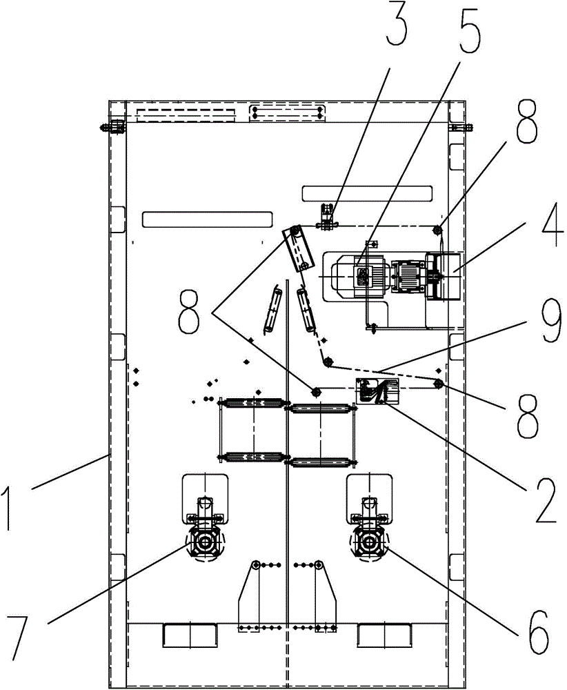
[0011] The crown belt conveying device of the present invention, as figure 1 As shown, it includes a frame 1, on which a material wheel, a material detection device 2, a material breaking clamping device 3 and a guide motor 5 equipped with a guide roller 4 are installed, and the material detection device 2 is located between the material wheel and the breaker. Between the material clamping device 3, the material wheel includes the first material wheel 6 and the second material wheel 7 located on both sides of the frame 1, the machine on both sides of the material detection device 2 and the two sides of the broken material clamping device 3 Guide rollers 8 are installed on the frame 1, and the material detection device 2 is electrically connected with the clamping device 3 for cutting off the material and the motor 5 for guiding.

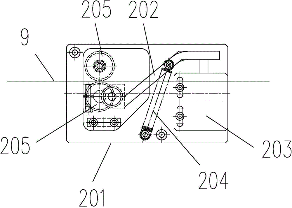
[0012] Such as figure 2 As shown, the material detection device 2 includes a detection base 201, a trigger lever 202, a micro switch 203, and a tr...


PUM


Abstract

The invention discloses a crowned strip conveying device. The crowned strip conveying device comprises a rack, wherein the rack is provided with material wheels, a material detection device, a broken material clamping device and an opening guiding motor, wherein the opening guiding motor is provided with an opening guiding roller; the crowned strip conveying device is provided with two material wheels, the situation that crowned strips on one material wheel are completely conveyed can be detected by the material detection device before the crowned strips are away from the crowned strip conveying device when the crowned strips on one material wheel are completely conveyed, the broken material clamping device can be controlled to clamp the crowned strips which are not away from the crowned strip conveying device, the opening guiding motor which is used for pulling the crowned strips can be controlled to stop, an operator can be reminded of replacing the crowned strips, the crowned strips are not completely away from the crowned strip conveying device at the moment, and the conveying of the crowned strips can be continuously carried out just by enabling a new crowned strip to follow. According to the crowned strip conveying device disclosed by the invention, the operation is simple, time and labor are saved, the situation that the crowned strips need to be installed again due to error operation is avoided, the continuity of tire production is maintained, and the efficiency of tire production is ensured.

Description

technical field [0001] The present invention relates to a conveying device, in particular to a conveying device for producing cap strips of tyres. Background technique [0002] In the tire forming process, there is a process of winding the crown tape. The current cap tape feeding device uses the active roller to extract the crown tape from the I-shaped wheel for storing the crown tape and feed it to the next step. In the process, the cap strip feeding device is only provided with a material wheel for placing the I-shape wheel. When the cap strips on the material wheel are conveyed, it is necessary to switch the new I-shape full of crown strips to the material. on the wheel, and connect the new crown strip to the previous crown strip. The replacement of materials requires personnel to guard. Once the guards are negligent, the supply of crown strips will be interrupted, and the production of tires will also be interrupted, which will affect the quality of tires. The produ...

Claims


Application Information

Patent Timeline
Patent Type & Authority Applications(China)
IPC IPC(8): B65H19/10
CPCB65H19/20B65H2220/00B65H2301/415B65H2402/50B65H2553/25
Inventor 陆永高刘培华王联韵赵衍刚
Owner 青岛海琅智能装备有限公司
Why Eureka
Try Eureka