Electrolytic tank magnetic field external compensation device

A compensation device and electrolytic cell technology, applied in the field of external compensation devices, can solve the problems of high investment cost, large compensation current at the flue end, and limited use of compensation methods, and achieve high current efficiency, reduce vertical magnetic fields, and solve the effects of magnetic field problems.

Inactive Publication Date: 2015-03-18
GUIYANG AL-MG DESIGN & RES INST
View PDF5 Cites 1 Cited by
  • Summary
  • Abstract
  • Description
  • Claims
  • Application Information

AI Technical Summary

Problems solved by technology

In order to compensate the influence of adjacent columns on the electrolytic cell, the compensation current at the flue end is often larger
This compensation method requires two sets of rectifier units to provide different current intensities, and the corresponding rectifier units must be matched according to the current intensity. As a result, the selection of rectifier units is limited and the investment cost is relatively high, so that the application of this compensation method is limited. larger limit

Method used


Image

  • Electrolytic tank magnetic field external compensation device

Examples


Embodiment 1

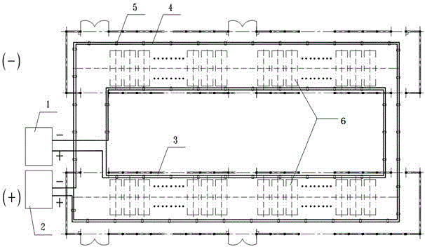
[0020] like figure 1 As shown, an external compensation device for the magnetic field of an electrolytic cell includes a series of electrolytic cells 6 arranged in parallel, a rectifier unit 1 at the flue end and a rectifier unit 2 at the aluminum outlet end. The flue end of the electrolytic cell 6 and the aluminum outlet end each form a closed loop with two turns. The flue end surrounds the busbar 3 and the aluminum outlet end surrounds the busbar 4 and is fixed by the busbar bracket 5. The surrounding busbar is an aluminum busbar with an aluminum content of 99.5%, and the flue end surrounds The busbar 3 and the aluminum outlet end surround the busbar 4 with the same diameter, and the current density around the busbar is 0.3A / mm 2 .

Embodiment 2

[0022] An external compensation device for the magnetic field of an electrolytic cell, comprising a series of electrolytic cells 6 arranged in parallel, a flue end rectifier unit 1 and an aluminum outlet end rectifier unit 2, the flue end surrounds the bus bar 3 and forms a three-turn closure along the flue end of the electrolytic cell 6 Circuit, the aluminum outlet end surrounds the busbar 4 and forms a closed loop with two turns along the electrolytic cell 6 aluminum outlet end, the flue end surrounds the busbar 3 and the aluminum outlet end surrounds the busbar 4 and is fixed by the busbar bracket 5, and the surrounding busbar is made of aluminum with an aluminum content of 99.6% The busbar, the flue end surrounds the busbar 3, and the aluminum outlet end surrounds the busbar 4 with the same diameter, and the current density around the busbar is 0.3A / mm 2 .

Embodiment 3

[0024] An external magnetic field compensation device for an electrolytic cell, comprising a series of electrolytic cells 6 arranged in parallel, a flue end rectifier unit 1 and an aluminum outlet end rectifier unit 2, the flue end surrounds a bus 3, and the aluminum outlet surrounds a bus 4 respectively along the electrolytic cell 6. The flue end and the aluminum outlet end each form a closed loop. The flue end surrounds the busbar 3 and the aluminum outlet end surrounds the busbar 4 and is fixed by the busbar bracket 5. The surrounding busbar is an aluminum busbar with an aluminum content of 99.7%. The current density around the busbar is 0.4A / mm 2 , and the diameter of the flue end surrounding the bus bar 3 is larger than the diameter of the aluminum outlet end surrounding the bus bar 4 . The alternating current passes through the flue end rectifier unit 1 and the aluminum outlet end rectifier unit 2 into different direct currents, and then is connected to the electrolysis ...


PUM


Abstract

The invention discloses an electrolytic tank magnetic field external compensation device which comprises an electrolytic tank (6), a flue end rectifier unit (1) and an aluminum output end rectifier unit (2); a flue end surrounding bus (3) leading out from the flue end rectifier unit (1) and an aluminum output end surrounding bus (4) leading out from the aluminum output end rectifier unit (2) respectively form closed loops along electrolytic tank (6) flue ends and aluminum output ends. Compared with the prior art, the device can flexibly select the rectifier units and adjust the value of a compensation current, is used for reduce investment of a traditional compensation mode, moreover, is flexible in configuration, can effectively optimize the magnetic field of the electrolytic tank, makes the electrolytic tank obtain reasonable bath internal magnetic field distribution and a stable melt flow velocity field, ensures the stability and relatively high current efficiency in an electrolytic tank production process, and at the same time, makes the bath surrounding bus configuration simplified.

Description

technical field [0001] The invention relates to an external compensation device for balancing the magnetic field of an electrolytic cell, belonging to the field of electrolytic aluminum equipment. Background technique [0002] The function of the electrolyzer bus system is to connect the cathode of the upper electrolyzer and the anode of the lower electrolyzer. Finally, hundreds of electrolyzers in the entire electrolysis series are connected in series through the bus system, and the powerful direct current is introduced into each electrolyzer through the bus to provide energy for the electrochemical reaction. . [0003] After electrification, a strong magnetic field (B) will be generated around the busbar. These strong magnetic fields interact with the current (J) in the melt of the electrolytic cell to generate electromagnetic force (F=JxB) in the melt zone. The distribution and magnitude of the electromagnetic force in the horizontal direction determines the flow form an...

Claims


Application Information

Patent Timeline
Patent Type & Authority Applications(China)
IPC IPC(8): C25C3/16
CPCC25C3/16
Inventor 傅长宏
Owner GUIYANG AL-MG DESIGN & RES INST
Why Eureka
Try Eureka