Unlock instant, AI-driven research and patent intelligence for your innovation.
Control system and method of water pump chain
What is Al technical title?
Al technical title is built by PatSnap Al team. It summarizes the technical point description of the patent document.
A technology of interlocking control and water pumps, applied in heating and ventilation control systems, heating and ventilation safety systems, heating methods, etc., can solve problems such as high cost, complicated engineering installation wiring, etc., and achieve the effect of saving costs and reducing wiring requirements
Active Publication Date: 2017-02-01
GREE ELECTRIC APPLIANCES INC
View PDF5 Cites 0 Cited by
Summary
Abstract
Description
Claims
Application Information
AI Technical Summary
This helps you quickly interpret patents by identifying the three key elements:
Problems solved by technology
Method used
Benefits of technology
Problems solved by technology
This control method is complicated in engineering installation and wiring, and the cost is relatively high.
Method used
Image
Click on the blue label to locate the original text in one second.
Reading with bidirectional positioning of images and text.
Examples
Embodiment 1
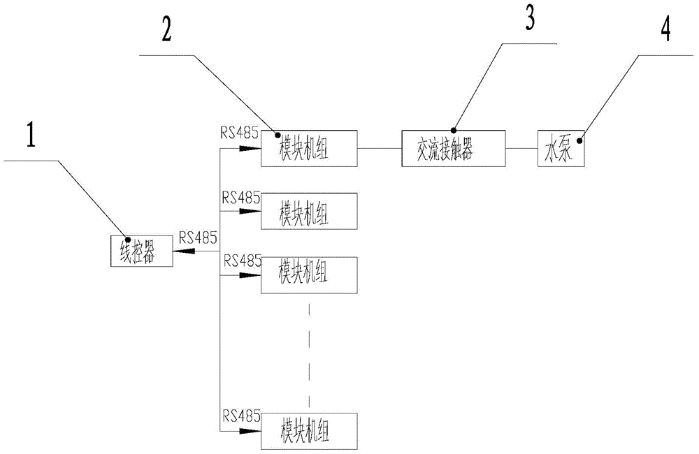
[0040] Embodiment one, as figure 1 , 2 As shown, a water pump chain control system includes a wire controller 1, a water pump 4 and several modular units 2;
[0041] The wire controller 1 is a prior art, and will not be described in detail here;
[0042] The wire controller 1 communicates with several modular units 2, and is used to receive the water pump start demand signal sent by several modular units 2, and send the signal to several modular units 2 after summarizing the signals, that is, each modular unit 2 has received all The water pump of the modular unit starts the demand signal;
[0043] The water pump 4 is electrically connected to any modular unit 2;
[0044] The modular unit connected to the water pump 4 judges whether there is a need to turn on the water pump according to the received aggregated demand signal, and controls the turning on and off of the water pump 4 .
[0045] Preferably, as a possible implementation of the present invention, the modular unit ...
Embodiment 2
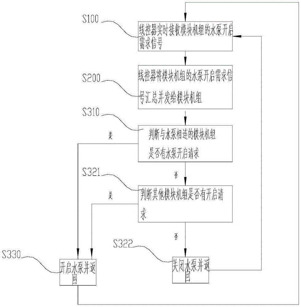
[0060] Embodiment two, such as image 3 As shown, a water pump interlock control method includes the following steps:
[0061] S100, the wire controller receives the water pump start demand signal of the module unit in real time;
[0062] S200, the wire controller summarizes the start demand signals of the water pumps of the modular units and sends them to the modular units respectively;
[0063] S300, the modular unit connected to the water pump judges whether there is a need to turn on the water pump, and controls the water pump to turn on or off according to the judgment result.
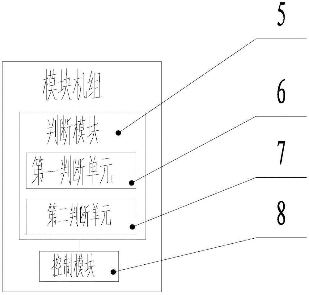
[0064] Among them, S300 means that after the modular unit connected to the water pump 4 receives the summary signal sent by the wire controller 1, the judging module 5 in the modular unit connected to the water pump 4 judges whether there is a need to turn on the water pump, and according to the judgment result by The control module 5 controls the water pump to be turned on or off. This judgmen...
PUM
Abstract
The invention provides a water pump interlockingcontrol system and method. The water pump interlockingcontrol system comprises a wire controller, a plurality of module units and a water pump, the wire controller is in communication connection with the module units, each module unit comprises a judgment module and a control module which are electrically connected, the water pump is electrically connected with the control module of an optional module unit, each judgment module is used for judging whether a water pump opening requirement exists or not, and each control module controls opening and closing of the water pump according to judgment results of the judgment module. The water pump interlocking control method includes the steps: receiving water pump opening requirement signals of the module units in real time by the wire controller; summarizing the water pump opening requirement signals of the module units and transmitting the signals to the module units by the wire controller; judging whether the water pump opening requirement exists or not by the module unit connected with the water pump, and controlling opening or closing of the water pump according to the judgment results. By the aid of the scheme, the water pump interlocking control system and the method have the advantages that wiring requirements are greatly reduced, and the cost of water pump connecting wires among an intermediate relay and the modules is omitted.
Description
technical field [0001] The invention relates to the field of air conditioning, in particular to a water pump chain control system and method. Background technique [0002] With the continuous advancement of science and technology and the improvement of people's living standards, the application of air conditioners in people's lives is becoming more and more extensive. The water system unit is an important part of the air conditioningsystem. [0003] At present, in the water system unit, each module controls the water pump according to its own needs. When the unit is modularly connected, the water pump outputs of all modules need to be connected in parallel through the central relay to control the water pump. This control method is complicated in engineering installation and wiring, and the cost is relatively high. Contents of the invention [0004] The purpose of the present invention is to provide a water pump chain control system and method, only need to connect the wa...
Claims
Application Information
Patent Timeline
Application Date:The date an application was filed.
Publication Date:The date a patent or application was officially published.
First Publication Date:The earliest publication date of a patent with the same application number.
Issue Date:Publication date of the patent grant document.
PCT Entry Date:The Entry date of PCT National Phase.
Estimated Expiry Date:The statutory expiry date of a patent right according to the Patent Law, and it is the longest term of protection that the patent right can achieve without the termination of the patent right due to other reasons(Term extension factor has been taken into account ).
Invalid Date:Actual expiry date is based on effective date or publication date of legal transaction data of invalid patent.
