Light sensing control method and light sensing control device

A control method and control device technology, applied in the field of CMOS photosensitive, can solve problems such as difficult HDR synthesis, too bright or too dark areas cannot coexist, and achieve the effect of avoiding overexposure and underexposure

Active Publication Date: 2015-03-18
LENOVO (BEIJING) CO LTD
View PDF4 Cites 19 Cited by
  • Summary
  • Abstract
  • Description
  • Claims
  • Application Information

AI Technical Summary

Problems solved by technology

[0004] In order to solve the problem that such over-bright or over-dark areas cannot coexist, high dynamic range image processing technolog

Method used


Image

  • Light sensing control method and light sensing control device
  • Light sensing control method and light sensing control device
  • Light sensing control method and light sensing control device

Examples


Embodiment Construction

[0024] Various embodiments according to the present invention will be described in detail with reference to the accompanying drawings. Here, it is to be noted that, in the drawings, the same reference numerals are assigned to components having substantially the same or similar structures and functions, and repeated descriptions about them will be omitted.

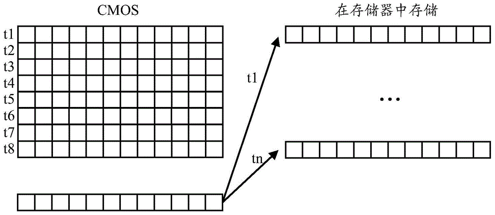
[0025] Such as figure 1 As shown, a schematic diagram of the photosensitive process of the existing CMOS photosensitive device is illustrated. In the photosensitive process of the existing CMOS photosensitive device, all sub-pixels are photosensitive according to the same exposure parameters, and after all sub-pixels are photosensitive according to the same exposure parameters, that is, after all sub-pixels are photosensitive, they are read row by row. The charge amount (or capacitance voltage) stored in the capacitance of each sub-pixel in each row of sub-pixels of the CMOS photosensitive device and the read-out charge am...


PUM


Abstract

The invention discloses a light sensing control method and a light sensing control device. The light sensing control method comprises the following steps: performing photometric analysis on a preview image of a collected scene, dividing the collected preview image into a plurality pixel regions, and calculating a light intensity value of each pixel region of the plurality of pixel regions; calculating the corresponding light sensing time of each pixel region of the collected preview image according to the calculated light intensity values of the plurality of pixel regions; and performing light sensing on each pixel region according to the corresponding light sensing time. By adopting the light sensing control method and the light sensing control device disclosed by the invention, phenomena of overexposure and underexposure possibly occur when too dark areas or too bright areas synchronously exist in a shoot scene can be effectively avoided.

Description

technical field [0001] The present invention relates to the field of CMOS photosensitive technology, and more particularly relates to a photosensitive control method and a photosensitive control device. Background technique [0002] Although CMOS photosensitive devices have been widely used in digital cameras, in many cases, due to the limited photosensitive area of ​​CMOS photosensitive devices, too dark or too bright areas in the shooting scene cannot coexist in images under the same exposure parameters. [0003] For example, when a CMOS photosensitive device generates 24-bit pixel data, the three colors of R, G, and B are 8 bits respectively, so the ratio of the maximum brightness and the minimum brightness that can be reflected by the sub-pixels of each of the three colors of R, G, and B should be at 2 8 within. In the shooting scene, the ratio of the maximum brightness to the minimum brightness of any of the three colors R, G, and B exceeds 2 8 In the case of the sam...

Claims


Application Information

Patent Timeline
IPC IPC(8): H04N5/235
Inventor 阳光
Owner LENOVO (BEIJING) CO LTD
Why Eureka
Try Eureka