Low-profile lighting system

A technology of components and lamps, which is applied in the field of lighting systems, can solve the problems of increasing the size of the wall washing system and strong constraints on the use of the wall washing system

Inactive Publication Date: 2015-03-18
SNAPTRACK
View PDF5 Cites 6 Cited by
  • Summary
  • Abstract
  • Description
  • Claims
  • Application Information

AI Technical Summary

Problems solved by technology

The use of such parabolic reflectors significantly increases the size of the wall washing system and imposes significant constraints on the use of the wall washing system

Method used


Image

  • Low-profile lighting system
  • Low-profile lighting system
  • Low-profile lighting system

Examples


Embodiment Construction

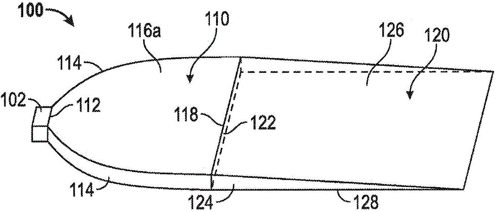
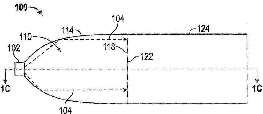
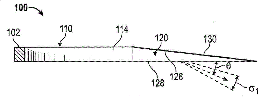
[0025] The following detailed description is directed to some implementations for the purposes of describing innovative aspects. However, the teachings herein can be applied in many different ways. While the teachings apply to light washing systems used with thin LED-based light engines, and in particular LED-based light engines that include light guides for directing the output of LED light sources in a desired pattern, the teachings also apply Any light washing system configured to operate on light emitted in a substantially collimated pattern. It is contemplated that the described implementations may be included in or associated with lighting for a wide variety of applications such as, but not limited to: commercial, industrial, and residential lighting. Embodiments may include, but are not limited to, homes, offices, manufacturing facilities, retail establishments, hospitals and clinics, convention centers, cultural institutions, libraries, schools, government buildings, ...


PUM


Abstract

This disclosure provides systems, methods and apparatus for providing a desired illumination pattern within a given plane. In one aspect, a light wash system can be configured to provide substantially even illumination on a wall or floor. The light wash system can use light-shaping optics such as a stack of optical films to provide a light wash system which is smaller than conventional light wash systems which utilize parabolic reflectors. The light wash system may include an internal retroreflector to allow a wider range of throw distances for the light wash system.

Description

technical field [0001] The present invention relates to lighting systems specifically for low profile light washing systems. Background technique [0002] A lighting system, such as a wall washer system, may be used to provide a generally uniform lighting pattern over a portion of a wall or ceiling to be illuminated. Such lighting systems may be used, for example, in art exhibitions or similar venues where uniform lighting of a specific area is desired without lighting the entire room or part of the room. Conventional wall washer systems utilize parabolic reflectors in order to achieve a substantially uniform light wash over the portion of the wall to be illuminated. The use of such parabolic reflectors significantly increases the size of the wall washing system and imposes significant constraints on the use of the wall washing system. Contents of the invention [0003] The systems, methods, and devices of the disclosure each have several innovative aspects, no single on...

Claims


Application Information

Patent Timeline
Patent Type & Authority Applications(China)
IPC IPC(8): F21K99/00F21S8/02F21V8/00
CPCY10T29/49826G02B6/0046G02B6/0073F21S8/026F21Y2105/00F21W2131/10F21K9/52F21V2200/20F21Y2101/02F21K9/61F21Y2115/10
Inventor 罗伯特·L·霍尔曼马修·B·桑普塞尔
Owner SNAPTRACK
Why Eureka
Try Eureka