Cleaning device

A technology for cleaning devices and cleaning chambers, which is applied in the directions of dry gas arrangement, cleaning method and utensils, and cleaning methods using liquids, etc., which can solve the problems of large dead angle cleaning, easy damage of workpieces, and reduced cleaning efficiency of workpieces, etc., and achieve good results. The effect of simple structure

Inactive Publication Date: 2015-03-25
CHANGZHOU YUJIA PACKAGING
View PDF0 Cites 0 Cited by
  • Summary
  • Abstract
  • Description
  • Claims
  • Application Information

AI Technical Summary

Problems solved by technology

[0002] The existing device for cleaning workpieces is generally a stirring type. The workpiece is easily damaged during cleaning, and there are l

Method used


Image

  • Cleaning device

Examples


Embodiment Construction

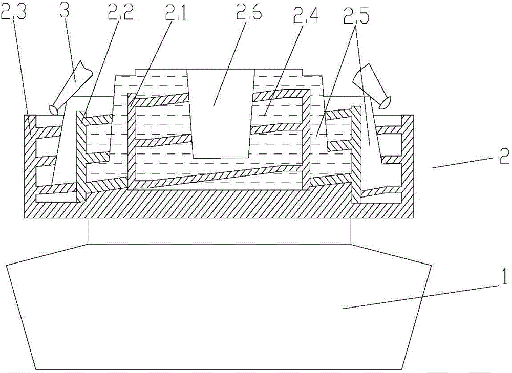
[0012] Such as figure 1 The shown cleaning device includes an electromagnetic vibrator 1, a cleaning hopper 2 on the electromagnetic vibrator 1, and the cleaning hopper 2 includes a concentrically arranged first rotary cleaning chamber 2.1, a second rotary cleaning chamber 2.2 and a second rotary cleaning chamber. The rotary air-drying chamber 2.3 on the periphery of chamber 2.2, the first rotary cleaning chamber 2.1, the second rotary cleaning chamber 2.2, and the rotary air-drying chamber 2.3 are all provided with upward spiral laminates, and a spiral cleaning channel 2.4 is formed between the spiral laminates. The height of the rotary cleaning chamber 2.2 is lower than that of the first rotary cleaning chamber 2.1, the outer wall of the first rotary cleaning chamber 2.1 is provided with a material channel 2.5 leading to the bottom of the second rotary cleaning chamber 2.2, and the height of the second rotary cleaning chamber 2.2 is higher than that of the rotary air-drying c...


PUM


Abstract

The invention relates to the technical field of cleaning devices, in particular to a cleaning device which comprises an electromagnetic vibrator and a cleaning hopper on the electromagnetic vibrator, wherein the cleaning hopper comprises rotary cleaning chambers and a rotary air-drying chamber surrounding the rotary cleaning chambers; upward spiral laminates are arranged in the rotary cleaning chambers and the rotary air-drying chamber; spiral cleaning channels and a spiral air-drying channel are formed by the upward spiral laminates; the rotary cleaning chambers are higher than the rotary air-drying chamber; a material channel is arranged on the outermost wall of one rotary cleaning chamber and extends from the upper part of the rotary cleaning chamber to the bottom of the rotary air-drying chamber; a cleaning solution is arranged in the spiral cleaning channels; a blowing nozzle for blowing air into the air-drying chamber is arranged above the rotary air-drying chamber; a feed channel extending downwards to the bottom of one rotary cleaning chamber is arranged at the axle center of the rotary cleaning chamber. The cleaning device can clean a workpiece and has the advantages of high effect, simple structure and high efficiency.

Description

technical field [0001] The invention relates to the technical field of cleaning devices, in particular to a cleaning device. Background technique [0002] The existing device for cleaning workpieces is generally a stirring type, and the workpieces are easily damaged during cleaning, and there are large dead angles during cleaning, which makes the cleaning of the workpieces not thorough enough and greatly reduces the efficiency of cleaning the workpieces. Contents of the invention [0003] The technical problem to be solved by the present invention is to provide a cleaning device with good effect, simple structure and high efficiency, aiming at the above defects. [0004] The technical scheme that the present invention solves its technical problem adopts is as follows: [0005] A cleaning device, comprising an electromagnetic vibrator and a cleaning hopper on the electromagnetic vibrator, the cleaning hopper includes a concentrically arranged rotary cleaning chamber and a ...

Claims


Application Information

Patent Timeline
IPC IPC(8): B08B3/10F26B21/00
CPCB08B3/10F26B21/00
Inventor 沈园园
Owner CHANGZHOU YUJIA PACKAGING
Why Eureka
Try Eureka