Steel element bending device

A bending device and bending technology, applied in the field of tools, can solve the problems of heavy labor intensity of workers, unsatisfactory bending effect, and difficult bending work, etc., and achieve the effect of good bending effect, simple structure, and small volume

Inactive Publication Date: 2015-03-25
GUANGXI UNIV
View PDF0 Cites 1 Cited by
  • Summary
  • Abstract
  • Description
  • Claims
  • Application Information

AI Technical Summary

Problems solved by technology

In the process of bending the steel element, it is often necessary to control the length of the bent part of the steel element and the bending angle of the steel element, which brings great dif

Method used


Image

  • Steel element bending device
  • Steel element bending device
  • Steel element bending device

Examples


Embodiment Construction

[0017] The present invention will be described in further detail below in conjunction with the accompanying drawings and specific implementation methods.

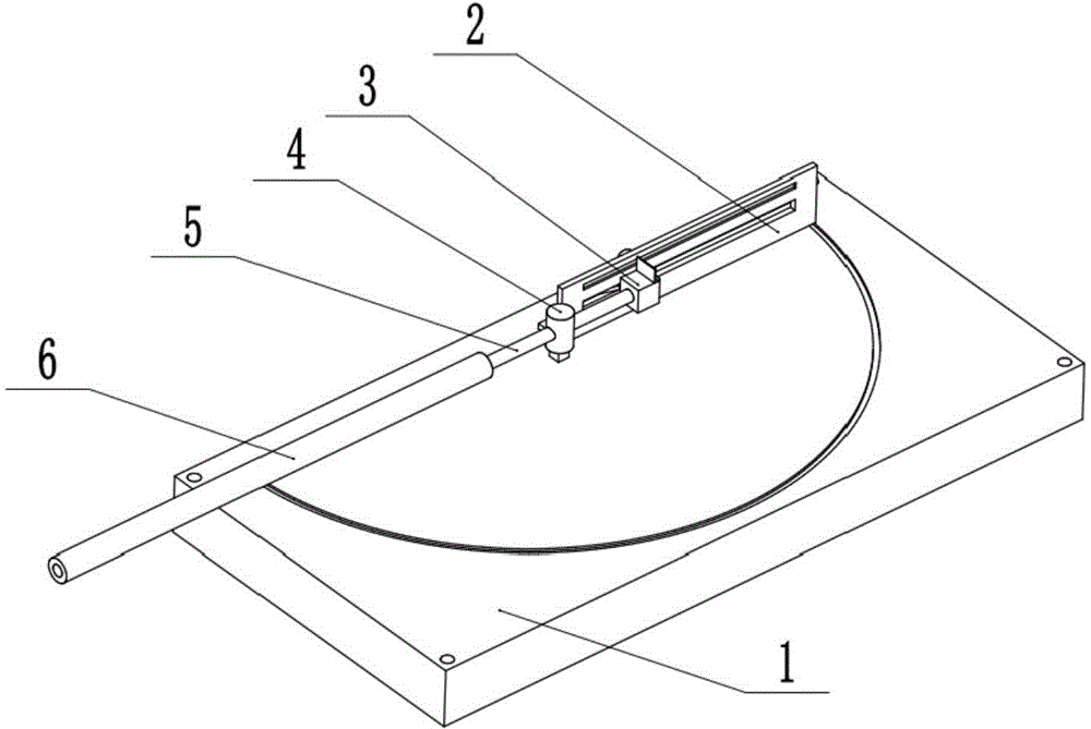
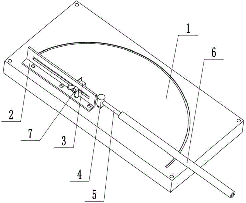
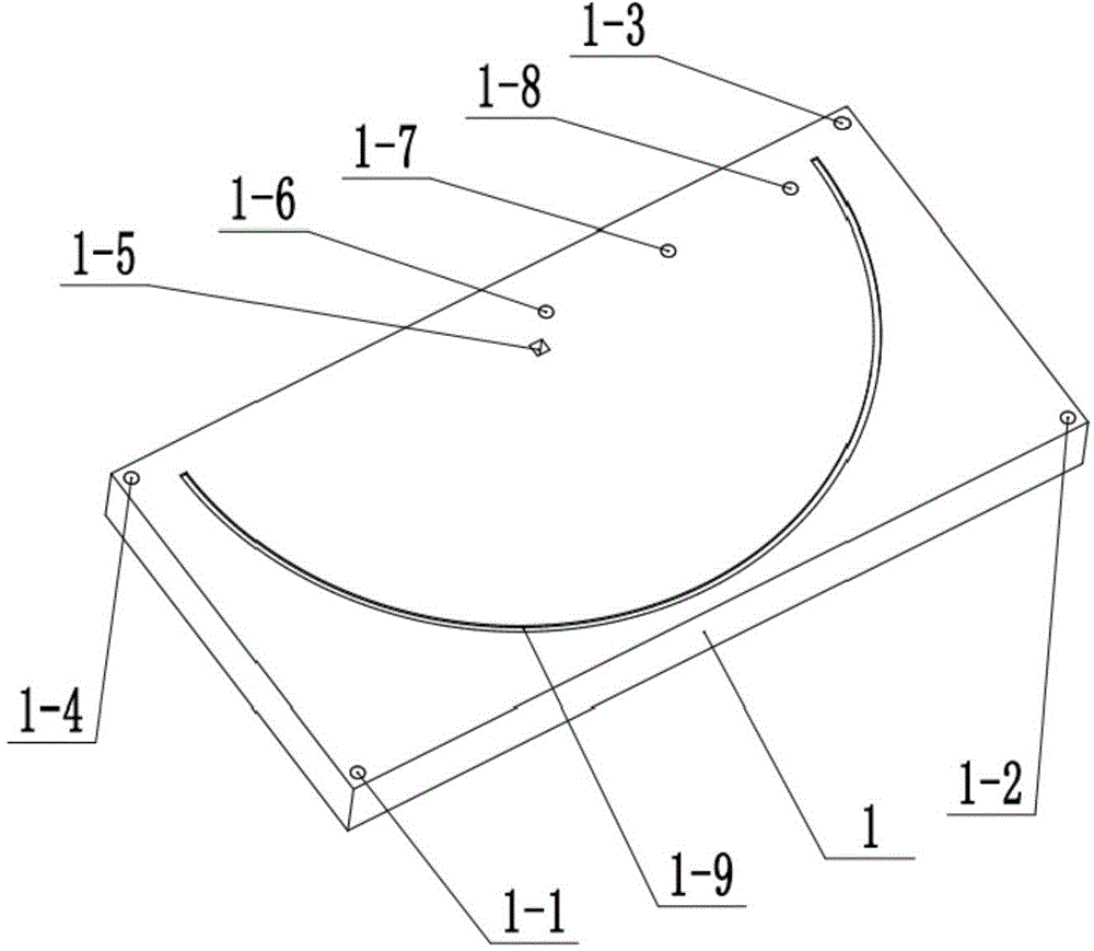
[0018] Such as Figure 1 to Figure 7 As shown, a steel element bending device according to the present invention includes a base 1 , a length scale 2 , a sliding block 3 , a bending column 4 , a push rod 6 and a wing nut 7 . Among them, the length scale 2 is fixedly connected to the base 1 through bolts; the bending column 4 is fixedly connected to the base 1 through interference fit with the first blind hole 1-5 on the base 1; the sliding block 3 is fixedly connected to the base 1 through a wing nut 7 is movably connected on the length scale 2, and can move horizontally in the chute 2-5 on the length scale 2, and is used for adjusting the length of the bending part of the steel element 5. When bending is required, first pass one end of the steel element 5 through the eighth through hole 4-2 on the bending column 4, and fi...


PUM


Abstract

The invention relates to a steel element bending device which comprises a base, a length scale plate, a slippage block, a bending column, a push rod and a butterfly nut. The length scale plate is fixed to the base, one end of the slippage block is a threaded column, a blind hole for fixing the end of a steel element is formed in the other end of the slippage block, and the threaded column is fixed to the length scale plate through the butterfly nut. The base portion of the bending column is fixed to the base, and a through hole for the steel element to penetrate through is formed in the head portion. The push rod is a hollow rod, one end of the steel element penetrates through the bending column and is fixed in the blind hole formed in the slippage block, the other end of the steel element is sleeved with the push rod, and the steel element is bent by turning the push rod under the effect of the bending column. The steel element bending device can adjust the length of the portion required to be bent of the steel element, can control the bending angle of the steel element and is convenient and practical to use.

Description

technical field [0001] The invention relates to a tool, in particular to a steel element bending device. Background technique [0002] In daily life, there are many tools that require the use of bent steel elements, such as harpoons and forks for roasting lamb. In the process of bending the steel element, it is often necessary to control the length of the bent part of the steel element and the bending angle of the steel element, which brings great difficulties to the bending work. At present, the bending steel element mainly adopts the manual bending method, that is, the steel element is pried and bent manually by tools such as wrench. ideal. Therefore, workers and masters need a steel element bending device that can not only adjust the length of the steel element to be bent, but also control the bending angle of the steel element. Contents of the invention [0003] The technical problem to be solved by the present invention is to provide a steel element bending device,...

Claims


Application Information

Patent Timeline
IPC IPC(8): B21D7/14
CPCB21D7/14
Inventor 张鲁云
Owner GUANGXI UNIV
Why Eureka
Try Eureka