Material transferring mechanism

A transfer mechanism and material technology, applied in the direction of conveyor objects, transportation and packaging, etc., can solve the problems of affecting products, low work efficiency, inaccurate feeding position, etc., and achieve the effect of saving space

Active Publication Date: 2015-03-25
BOZHON PRECISION IND TECH CO LTD
View PDF6 Cites 26 Cited by
  • Summary
  • Abstract
  • Description
  • Claims
  • Application Information

AI Technical Summary

Problems solved by technology

In the prior art, the manual reciprocating feeding is generally used, which has high labor intensity, low work...

Method used


Image

  • Material transferring mechanism
  • Material transferring mechanism

Examples


Embodiment Construction

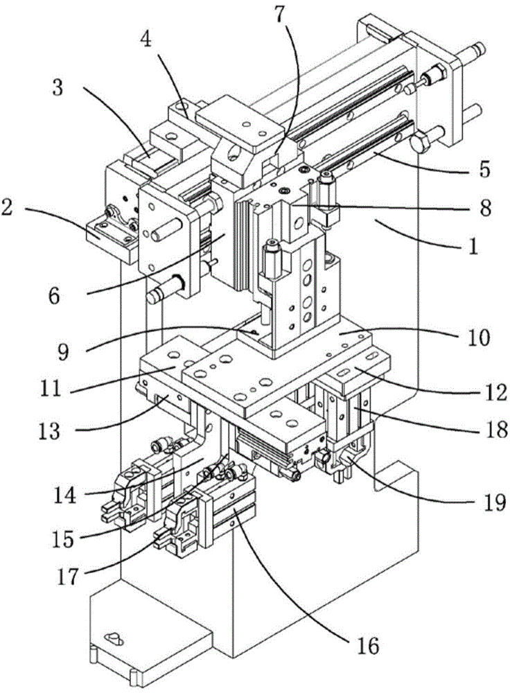
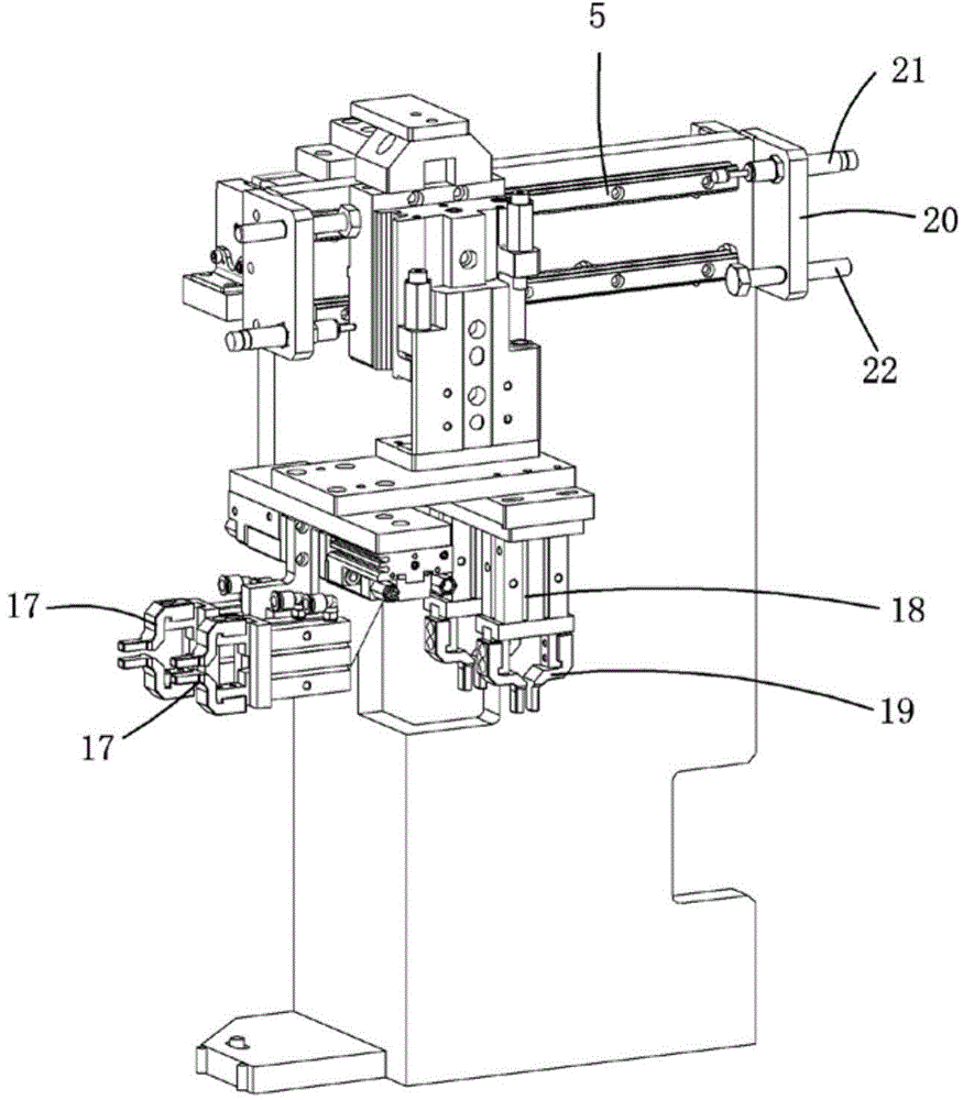
[0015] Examples, see attached figure 1 with 2 , a material transfer mechanism, which includes a mounting plate 1, a horizontal cylinder fixing plate 2 is fixedly installed on the back of the mounting plate, a horizontal cylinder 3 is installed on the horizontal cylinder fixing plate, and a horizontal moving plate 4 is installed on the piston rod of the horizontal cylinder Two transverse slide rails 5 are fixedly installed on the front of the mounting plate, and a transverse slide block is installed on each transverse slide rail, and a lifting cylinder mounting plate 6 is installed on the two transverse slide blocks; the lifting cylinder mounting plate A moving block 7 is installed on the upper end of the moving block, and a square slot hole is provided on the moving block. The horizontal moving plate is a square plate, and the square plate can be inserted into the square slot hole for fixing, so that the horizontal moving plate and the moving block are fixedly connected togeth...


PUM


Abstract

The invention relates to a material transferring mechanism. A horizontal cylinder fixing plate is fixedly mounted at the back of a mounting plate, a horizontal cylinder is mounted on the horizontal cylinder fixing plate, and a horizontal moving plate is mounted on the horizontal cylinder; lateral sliding rails are fixedly mounted in the front of the mounting plate, lateral sliding blocks are mounted on the lateral sliding rails, and a lifting cylinder mounting plate is mounted on the lateral sliding blocks; a moving block is mounted at the upper end of the lifting cylinder mounting plate, a lifting cylinder is mounted on the front side of the lifting cylinder mounting plate, the horizontal moving plate is fixed on the moving block, and a clamping jaw cylinder mounting plate is fixedly mounted at the lower end of the lifting cylinder through a lifting plate; a switching cylinder fixing plate and a material receiving cylinder fixing plate are mounted at the lower part of the clamping jaw cylinder mounting plate; switching cylinders are mounted at the lower part of the switching cylinder fixing plate, and the switching cylinders are connected to switching plates; material taking cylinders are mounted on the switching plates, and material taking clamping jaws are mounted on the material taking cylinders; material receiving cylinders are mounted at the lower part of a material receiving cylinder fixing plate, and material receiving clamping jaws are mounted on the material receiving cylinders. Through adoption of the material transferring mechanism disclosed by the invention, materials can be taken in a horizontal direction, and can be received in a perpendicular direction, so that products are transported to a standard position.

Description

Technical field: [0001] The invention relates to the field of material transfer mechanism equipment, and more specifically relates to a material transfer mechanism that can take materials from a material belt, and can also receive materials from other mechanisms and transport materials to standard operating positions. Background technique: [0002] In the assembly line operation process of the production workshop, the products are generally placed on the material belt, and the material belt is generally placed on the support plate. After the final product needs to be rotated by 90°, the other material receiving mechanism will receive the material, and then proceed to the next step. In this process, a material transfer mechanism that can take the material and receive the material from other mechanisms is needed to transport the material to the standard working position. In the prior art, the materials are generally reciprocated manually, which is labor-intensive, low in effi...

Claims


Application Information

Patent Timeline
IPC IPC(8): B65G47/248B65G47/90B65G47/52
Inventor 吕绍林陈小刚陈骅张长辉
Owner BOZHON PRECISION IND TECH CO LTD
Why Eureka
Try Eureka