
Screed plate and paver

A technology of screeds and board frames, applied in roads, road repairs, roads, etc., can solve the problems of increasing labor intensity and management difficulty, affecting construction quality, and increasing construction costs, so as to reduce the number of alternatives and reduce management difficulty and construction cost, reduce labor intensity and time effect

Active Publication Date: 2015-03-25
湖南三一中益机械有限公司
View PDF5 Cites 0 Cited by
  • Summary
  • Abstract
  • Description
  • Claims
  • Application Information

AI Technical Summary

Problems solved by technology

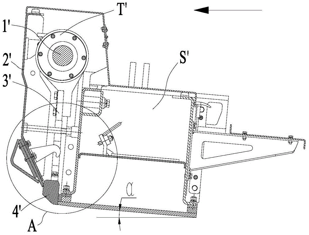
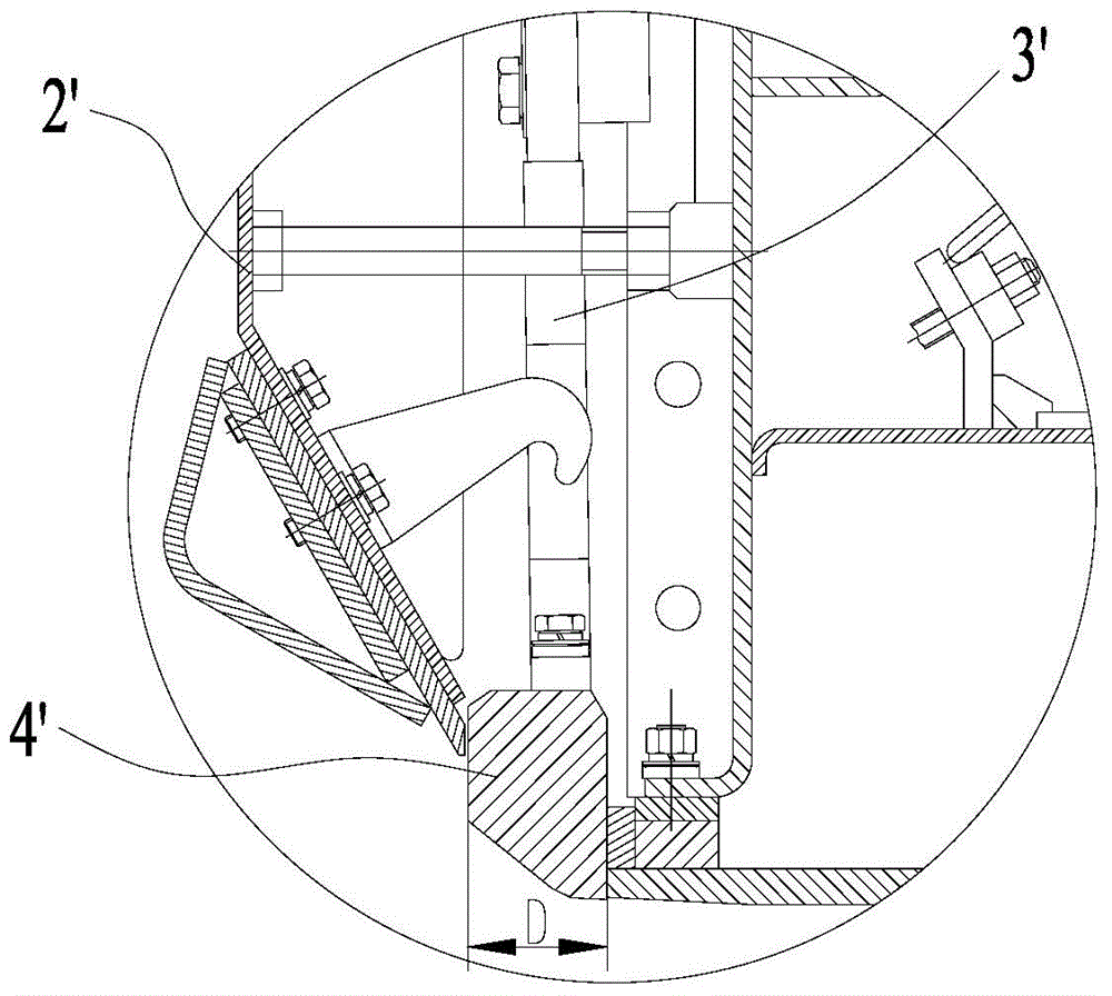
[0004] However, the wider blade 4' is not all beneficial: the wider blade 4' can increase the degree of pre-compaction when building stable soil roads, especially when using a telescopic screed. , so that the working elevation angle α is reduced to achieve large-thickness paving, and because the stable soil stiffness is small, the reverse impact force received by the blade 4' with a larger width is also small, and the vibration of the screed will not increase too much, so the blade 4' with a larger width The blade 4' is more suitable for the construction of stable soil pavement; when building asphalt pavement, due to the high rigidity of the asphalt mixture, the blade 4' with a larger width receives a relatively large reverse impact force of the material, causing the screed to vibrate or even jump, affecting the construction quality, and the thickness of the asphalt pavement is generally not large, so it is more appropriate to use a common blade 4' with a smaller width for construction
Therefore, when constructing different road materials, it is necessary to use different pavers or replace blades 4' of different widths for construction, which not only wastes time, increases construction costs, but also increases labor intensity and management difficulty

Method used


Image

  • Screed plate and paver
  • Screed plate and paver
  • Screed plate and paver

Examples


Embodiment Construction

[0027] It should be noted that, in the case of no conflict, the embodiments of the present invention and the features in the embodiments can be combined with each other. The following will refer to the attached Figure 3-8 The present invention will be described in detail in combination with examples. "Front" in this article refers to the paving direction of the paver, that is, the driving direction of the paver during construction, that is, figure 1 In the direction indicated by the middle arrow, the first material blocking surface 41 of the first blade 4 and the second material blocking surface 51 of the second blade 5 are surfaces facing the above-mentioned “front”.

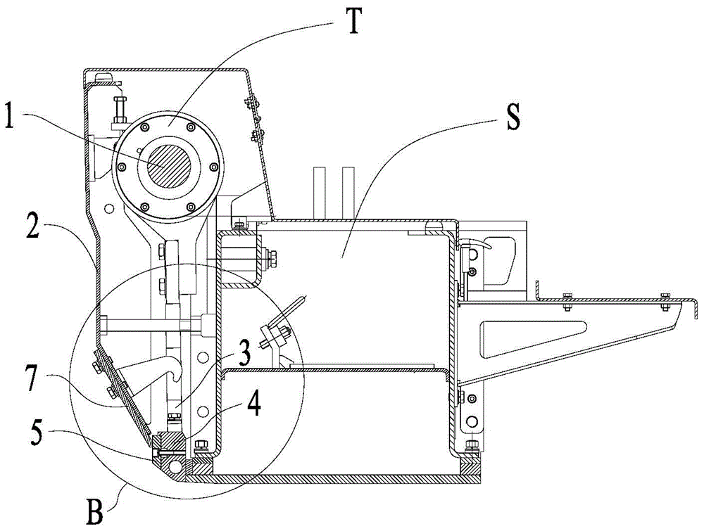
[0028] Such as Figure 3-6 As shown, the specific embodiment of the present invention provides a screed, including a plate frame S, a material retaining plate 2 and a vibrating mechanism T, the material retaining plate 2 is arranged in front of the plate frame S, and the material retaining plate 2 and the pl...


PUM


Abstract

The invention discloses a screed plate and a paver. The screed plate comprises a plate rack, a striker plate and a vibrating mechanism, wherein the striker plate is arranged in front of the plate rack; the vibrating mechanism is arranged in a space between the striker plate and the plate rack, and comprises an eccentric shaft, a connecting rod, a first blade and a second blade; the upper end of the connecting rod is connected with the eccentric shaft, and the lower end of the connecting rod is connected with the upper end surface of the first blade; and the second blade is detachably arranged on a stopping surface of the first blade. According to the blades of the screed plate, a detachable assembling structure of the first blade and the second blade is adopted, and construction of different road building materials can be met. In addition, according to construction under different working conditions, only the second blade needs to be detached or mounted, blades with different widths do not need to be replaced, and a paver do not need to be replaced. Therefore, the labor intensity is alleviated and time is shortened, and the alterative number of the blades can be reduced, so the management difficulty and construction cost are reduced.

Description

technical field [0001] The invention relates to the field of road construction machinery, in particular to a screed and a paver. Background technique [0002] The paver is a kind of equipment that spreads the mixed road construction materials on the roadbed according to a certain thickness and pre-compacts them. The effect of pre-compaction not only affects the number of rolling passes and work efficiency of subsequent road rollers, but also affects the flatness of the formed road surface. [0003] At present, in addition to increasing the rotational speed of the vibrating mechanism T' eccentric shaft 1' and the vertical stroke of the blade, it is also possible to install a blade with a larger width on the screed to increase the pre-compaction degree. Such as figure 1 and figure 2 As shown, the blade 4' with a larger width is installed on the screed. Specifically, the vibrating mechanism T' is installed on the screed, and the vibrating mechanism T' is located between the...

Claims


Application Information

Patent Timeline
IPC IPC(8): E01C19/48
CPCE01C19/4833
Inventor 胡建标吴沙谢金龙
Owner 湖南三一中益机械有限公司
Learn More