Valve connector capable of preventing mistaken closing
A technology of connectors and valves, applied in pneumatic brakes, railway car body parts, transportation and packaging, etc., can solve the problems that the angle cock door cannot be completely prevented from being closed by mistake, and the problem of the angle cock door closing has not been fundamentally solved. Achieve the effect of saving labor intensity and time and ensuring driving safety
- Summary
- Abstract
- Description
- Claims
- Application Information
AI Technical Summary
Problems solved by technology
Method used
Image
Examples
Embodiment 1
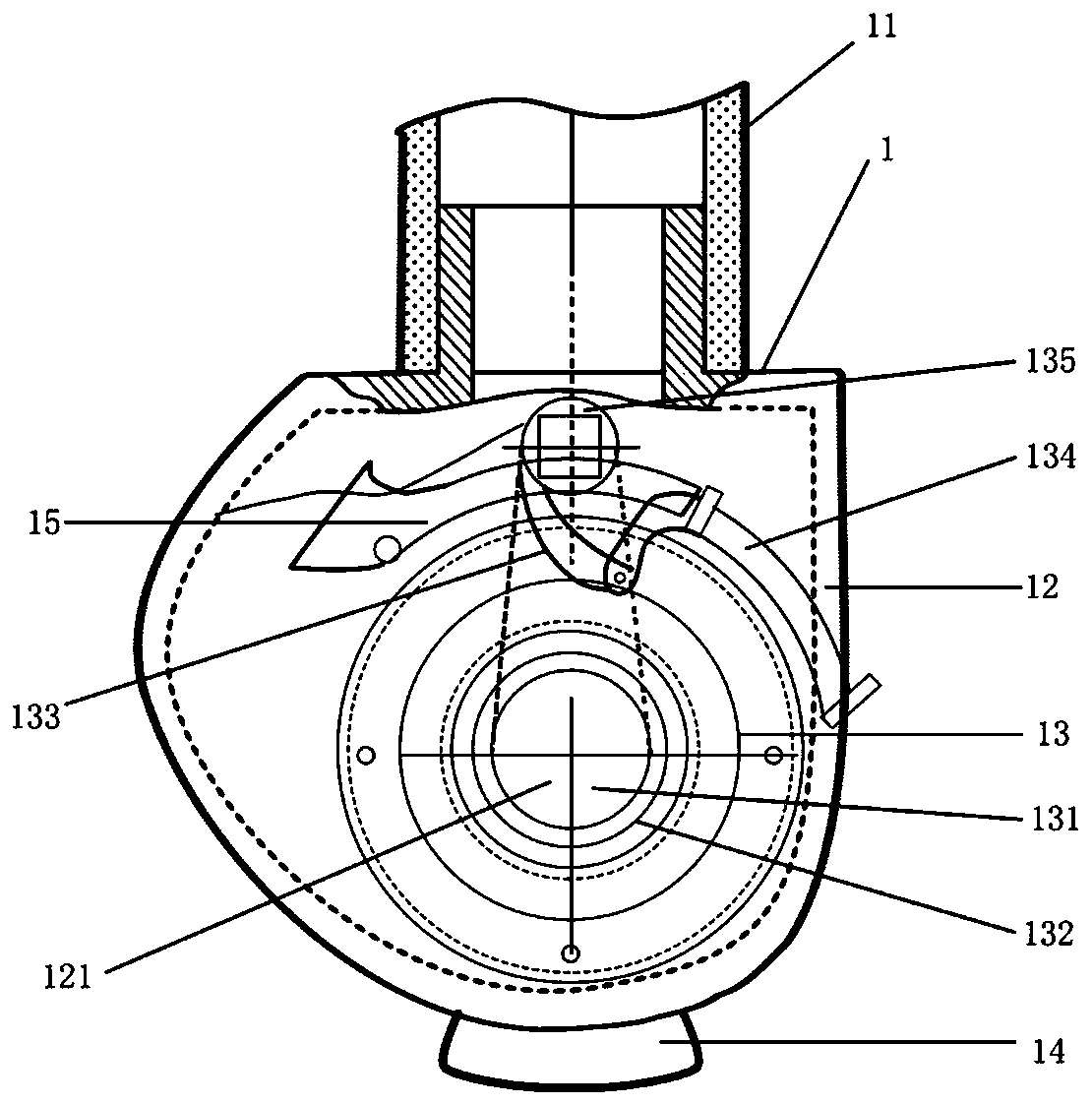
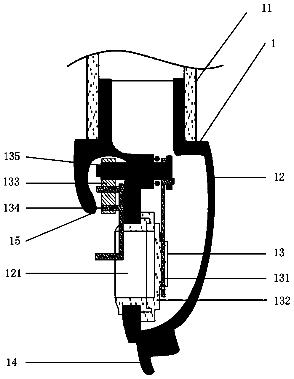
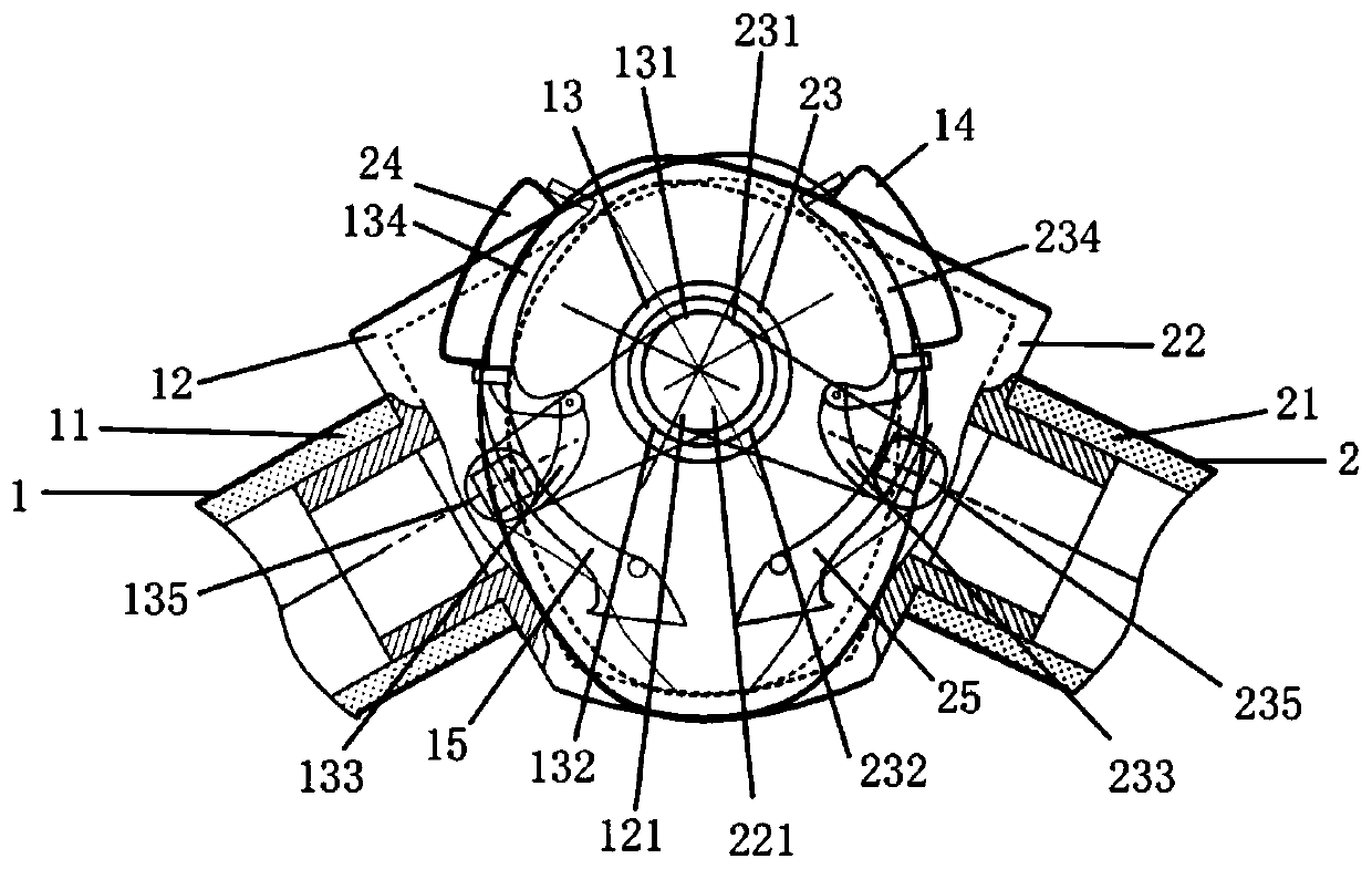
[0023] First, refer to Figure 1 ~ Figure 3 The valve connector and the connection structure of two valve connectors involved in Embodiment 1 of the present invention will be described as follows.
[0024] As shown in the figure, the valve connector 1 has a main pipe 11 connected by a fluid pipeline, a connecting head 12 connected to the main pipe, a connecting port 121 on the connecting head, and a sealing structure is arranged on the inner wall of the connecting port 121, and is installed inside the connecting head 12 The valve 13; wherein the valve 13 has a valve core 131, a valve seat 132 and a control structure valve handle 133; the control structure valve handle 133 includes making the valve 13 when the valve connector 1 is not connected to another valve connector 2 2 o'clock keep the reset device (not shown) that closes, and it can be magnetic force or elastic force etc. When the valve connector one 1 is connected to another valve connector two 2 , the force bearing me...
Embodiment 2
[0029] as attached Figure 4 As shown, the two valve connectors 1 and 2 in Embodiment 2 of the present invention are generally in the same structure as the valve connectors 1 and 2 involved in Embodiment 1, and the only difference lies in the structure of the valve 13 and the force-bearing part 134 There are differences in the settings. Meanwhile, the structures of the connected valve connectors 1 and 2 are exactly the same.
[0030]First, the force-bearing part 134 of the valve connector 1 is located at the end of the valve handle 133, on which the permanent magnet 136 is arranged, and the permanent magnet 141 is also arranged on the force-applying part 14, while another valve connector 2 2 is connected to the valve Device 1 has exactly the same structure. When the valve connector one 1 is connected with another valve connector two 2, the force-applying parts 14, 15 can drive the force-bearing parts 134, 234 in contact or non-contact through the attraction or repulsion forc...
Embodiment 3
[0033] as attached Figure 5 As shown, the two valve connectors 1 , 2 in Embodiment 3 of the present invention are substantially identical in structure to the valve connectors 1 , 2 involved in Embodiment 1, and the only difference lies in the structure of the valve 13 . Meanwhile, the structures of the connected valve connectors 1 and 2 are exactly the same. Any one of the ones described in Embodiments 1 and 2 can be used as the force-bearing part of the valve connector.
[0034] Compared with Embodiment 1, the valve handle shaft in Embodiment 3 is no longer directly connected to the valve core through the swing arm, but is directly arranged on the inner wall of the connecting head. as attached Figure 5 As shown, the valve handle 133 of the valve connector 1 is directly connected to the valve core 131 , and the end of the valve core 131 is rotatably connected to the inner wall of the connector 12 through the valve handle shaft 135 . Correspondingly, the shape of the valve...
PUM
 Abstract
Description
Claims
Application Information
 - R&D
- Intellectual Property
- Life Sciences
- Materials
- Tech Scout
- Unparalleled Data Quality
- Higher Quality Content
- 60% Fewer Hallucinations
Browse by: Latest US Patents, China's latest patents, Technical Efficacy Thesaurus, Application Domain, Technology Topic, Popular Technical Reports.
© 2025 PatSnap. All rights reserved.Legal|Privacy policy|Modern Slavery Act Transparency Statement|Sitemap|About US| Contact US: help@patsnap.com


