Drainage valve for electric device box

A technology for electrical equipment boxes and drain valves, applied to mechanical equipment, steam traps, etc., can solve problems such as poor sealing effect, inability to repair, poor sealing, etc., to reduce precision processing costs, reduce failure rates, and occupy space small effect

Inactive Publication Date: 2015-03-25
CRRC NANJING PUZHEN CO LTD
View PDF6 Cites 0 Cited by
  • Summary
  • Abstract
  • Description
  • Claims
  • Application Information

AI Technical Summary

Problems solved by technology

The drain valve is an integral structure and cannot be repaired
Since the sealing effect of the drain valve is mainly sealed by glue, poor sealing or operator error often results in poor sealing effect or even water seepage

Method used


Image

  • Drainage valve for electric device box
  • Drainage valve for electric device box

Examples


Embodiment Construction

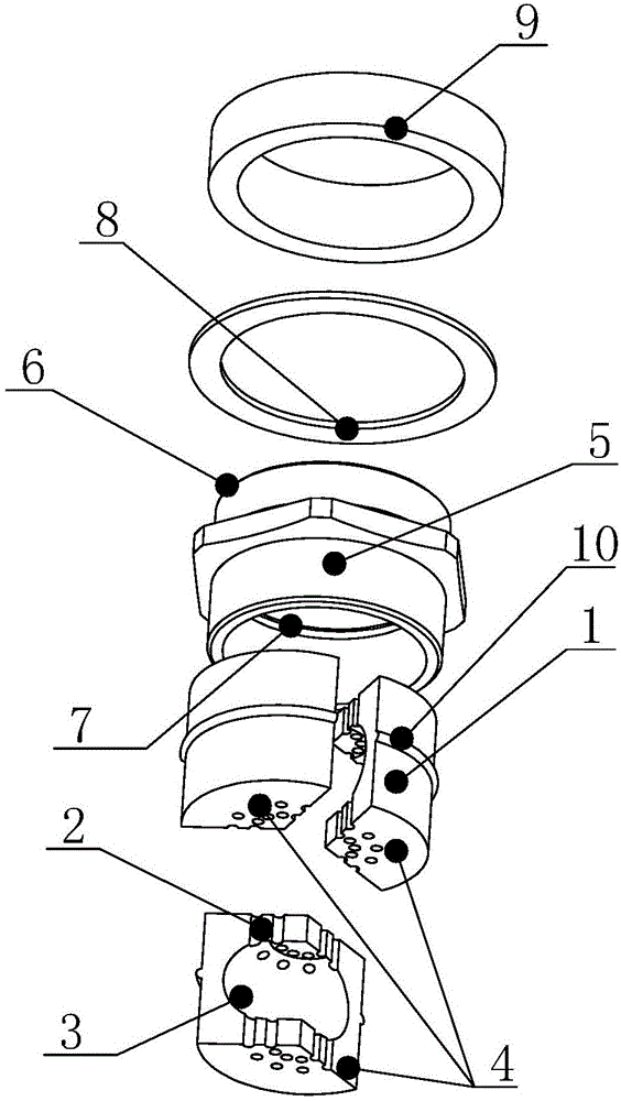
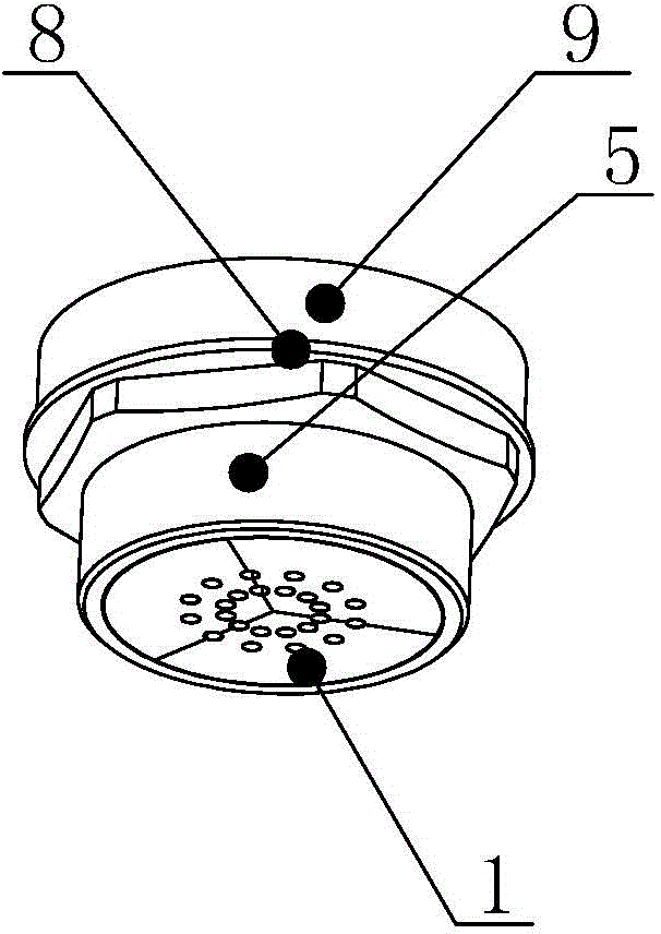
[0026] Such as figure 1 As shown, the drain valve for the electrical equipment box in this embodiment includes: a casing 5 threadedly connected to the casing, a rubber sealing gasket 8 arranged between the reserved internal thread boss 9 of the casing and the casing 5, the casing 5. The rubber sealing block 1 is installed inside. The rubber sealing block 1 has a condensation chamber 3 inside. The upper and lower parts of the rubber sealing block 1 have capillary holes 2 connected with the condensation chamber 3. The capillary holes 2 penetrate to the upper and lower surfaces of the rubber sealing block 1. , the rubber sealing block 1 is assembled from 3 to 4 vertically cut sub-blocks 4 . The inner wall of the casing 5 defines an annular groove 7 along the radial direction, and the side wall of the rubber block has an annular protrusion 10 , and the annular protrusion 10 is embedded in the annular groove 7 for positioning.

[0027] The installation method of the drain valve fo...


PUM


Abstract

The invention provides a drainage valve for an electric device box. The drainage valve for the electric device box comprises a shell and a sealing ring, wherein the shell is connected with a box body in a threaded mode, the sealing ring is arranged between an internally threaded boss and the shell, the internally threaded boss is reserved in the box body, a rubber sealing block is installed in the shell, a condensation cavity is formed in the rubber sealing block, the upper portion and the lower portion of the rubber sealing block are each provided with capillary pores communicated with the condensation cavity, the capillary pores penetrate through the upper surface and the lower surface of the rubber sealing block, and the rubber sealing block is formed by splicing three to four vertically cut sub-blocks. According to the drainage valve for the electric device box, the liquid capillary phenomenon is adopted to guide moisture in the box body to flow out of the drainage valve through capillary tubes, the drainage valve condenses and gathers the moisture into water drops through a hollow structure, the condensed water drops are discharged out of the box body through an external drainage pipe, and the drainage valve integrates the function of releasing air pressure in the box body through the deformability of a rubber product in the drainage valve.

Description

technical field [0001] The invention relates to a drain valve for an electrical equipment box. Background technique [0002] With the development of subway vehicle technology, there are more and more vehicle functions. The vehicle electrical equipment box has become complex in structure and has a wide variety of equipment and components. Especially for the electrical equipment box used outside the vehicle, the use environment is relatively complicated, and the equipment box needs to have the effect of waterproof, dustproof and sealing. This conflicts with the requirements for drainage and condensation of the equipment box, and effective drainage of water vapor inside the equipment box is also an essential requirement for vehicle safety. [0003] In the current drainage and sealing schemes used in vehicle equipment, drainage valves and explosion-proof membranes are mainly used to achieve the effects of drainage and protection. The installation of the drain valve is more com...

Claims


Application Information

Patent Timeline
Patent Type & Authority Applications(China)
IPC IPC(8): F16T1/00
Inventor 夏峰张凯黄沈阅鲍伟兵施晓芳时蒙胡斌谢建新梁师嵩胡小艳
Owner CRRC NANJING PUZHEN CO LTD
Why Eureka
Try Eureka