
Target correcting method of airborne fire-control radar antenna

A radar antenna and target calibration technology, which is applied in the field of aircraft radar, can solve the problems of different antenna calibration error values ​​and time consumption.

Inactive Publication Date: 2015-03-25
JIANGXI HONGDU AVIATION IND GRP
View PDF3 Cites 4 Cited by
  • Summary
  • Abstract
  • Description
  • Claims
  • Application Information

AI Technical Summary

Problems solved by technology

The problem with this calibration method is that every time the antenna is removed and reinstalled, the radar antenna must be calibrated again, which consumes a lot of time; at the same time, due to human factors, the antenna calibration errors measured by different people different value

Method used


Image

  • Target correcting method of airborne fire-control radar antenna
  • Target correcting method of airborne fire-control radar antenna
  • Target correcting method of airborne fire-control radar antenna

Examples


Embodiment Construction

[0022] The present invention is described in detail below in conjunction with accompanying drawing:

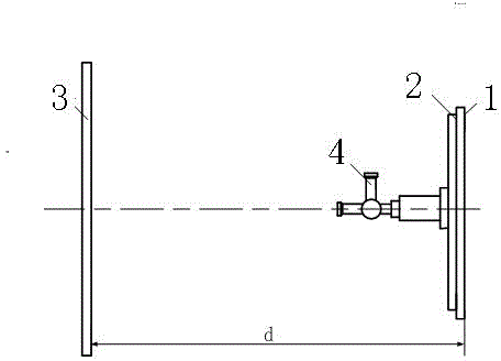
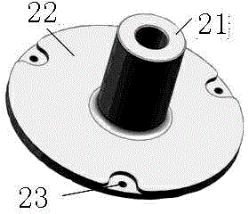
[0023] A method for calibrating a target of an airborne fire control radar antenna, the method comprising adopting a calibrating fixture 2; The frame frame plate frame 1 closely fits; the target calibration mirror mounting tube 21 on the clamp plate 22 of the target calibration fixture 2 is used to place the target calibration mirror 4;

[0024] It is characterized in that: the specific steps of the method are as follows:

[0025] h) Before calibration, level the aircraft first;

[0026] i) Place the target board 3 at a distance d≈D0 m from the front end of the radar antenna front, and record the data, and adjust the target board so that the longitudinal axis and horizontal axis of the target board are respectively in line with the symmetry axis of the aircraft and the horizontal datum line coincidence;

[0027] j) The target calibration fixture 2 is installed on the fi...


PUM


Abstract

The invention relates to a target correcting method of an airborne fire-control radar antenna, and belongs to the field of aircraft radar. A target correcting clamp is involved in the method, fixed to an aircraft frame plate through installing holes, and tightly attached to the aircraft frame plate. A target correcting lens installing tube arranged on a target correcting clamp plate is used for installing a target correcting lens. When the radar antenna is reinstalled, error data of previous target correcting can be directly adopted for error binding, and target correcting does not need to be performed again.

Description

technical field [0001] The invention relates to a target calibration method for an airborne fire control radar antenna, which belongs to the field of aircraft radar. Background technique [0002] In the field of radar, the radar antenna detects the target by transmitting and receiving electromagnetic waves, including the distance, speed, and orientation information of the target. Generally, errors in the installation of the radar antenna may cause deviations in the detected target positions, so error calibration is required for the installation of the radar antenna. [0003] The airborne fire control radar antenna is installed in front of the first frame of the aircraft. In the radar antenna target calibration, the radar antenna is installed on the aircraft first, and then the relevant data is measured, that is, the target calibration is performed on the antenna installed on the aircraft. The problem with this calibration method is that every time the antenna is removed an...

Claims


Application Information

Patent Timeline
Patent Type & Authority Applications(China)
IPC IPC(8): G01S7/40
CPCG01S7/4026
Inventor 陈亮
Owner JIANGXI HONGDU AVIATION IND GRP
Learn More