Target correcting device of airborne fire control radar antenna

A radar antenna and target calibration technology, which is applied to antenna supports/installation devices, radio wave measurement systems, instruments, etc., can solve problems such as complex calculations, inaccurate calibration, and inability to meet long-distance calibration needs. Avoid complex effects

Pending Publication Date: 2022-04-19
XIAN AIRCRAFT DESIGN INST OF AVIATION IND OF CHINA
View PDF0 Cites 0 Cited by
  • Summary
  • Abstract
  • Description
  • Claims
  • Application Information

AI Technical Summary

Problems solved by technology

[0003] 1. There is a large deviation in visual target calibration itself, which leads to inaccurate target calibration or aggravates the deviation before target calibration
[0004] 2. The target calibration distance of the target calibration mirror of the visual target calibration method is limited, which cannot meet the long-distance target calibration requirements. The effective distance of the traditional target calibration mirror is no more than 50 meters, while the current target calibration distance is more than 250 meters. above requirements
[0005] 3. The traditional target calibration device requires complex calculations after calibration, which is time-consuming and laborious

Method used


Image

  • Target correcting device of airborne fire control radar antenna
  • Target correcting device of airborne fire control radar antenna
  • Target correcting device of airborne fire control radar antenna

Examples


Embodiment Construction

[0041] The technical solutions of the present invention will be further described below in conjunction with the accompanying drawings and through specific implementation methods.

[0042] Wherein, the accompanying drawings are only for illustrative purposes, showing only schematic diagrams, rather than physical drawings, and should not be construed as limitations on this patent; in order to better illustrate the embodiments of the present invention, some parts of the accompanying drawings will be omitted, Enlarged or reduced, does not represent actual product size.

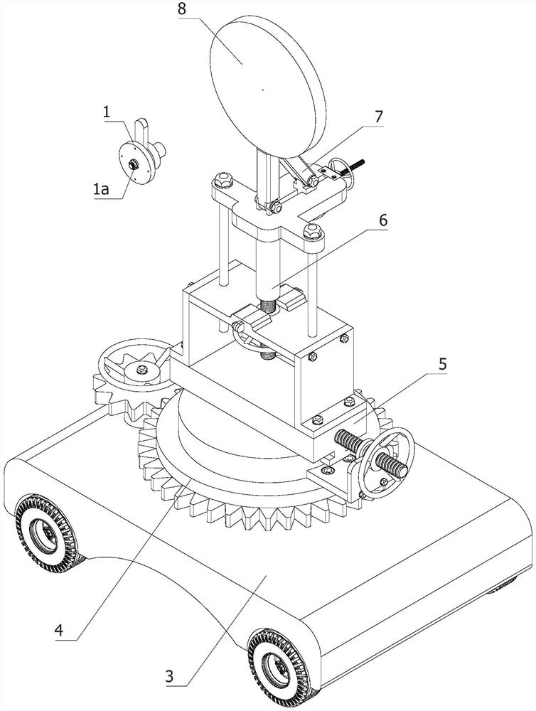
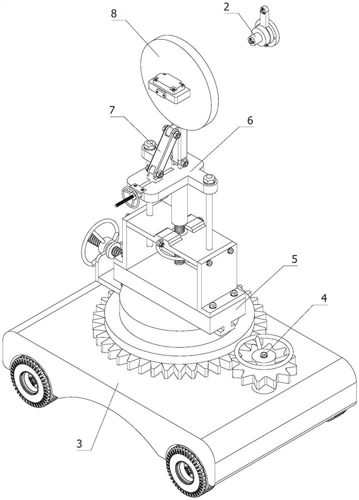
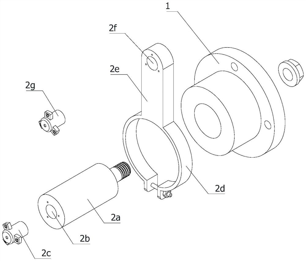
[0043] refer to Figure 1 to Figure 9 The shown target calibration device for an airborne fire control radar antenna includes a radar turntable 1 and an antenna mount 1a, and also includes a laser target calibration device 2, a target plate base 3, a rotation adjustment mechanism 4, a translation adjustment mechanism 5, a lift The adjustment mechanism 6, the pitch adjustment mechanism 7 and the target plate mecha...


PUM


Abstract

The invention relates to the field of radar antenna boresighting, in particular to a boresighting device of an airborne fire control radar antenna, which comprises a laser boresighting device, a target plate base, a rotation adjusting mechanism, a translation adjusting mechanism, a lifting adjusting mechanism, a pitching adjusting mechanism and a target plate mechanism. The laser target correcting device solves the problem that target correcting is inaccurate or deviation is caused before target correcting is aggravated due to the fact that large deviation exists in visual target correcting. The problems that the target correction distance of a target correction mirror in a traditional visual target correction method is limited, the long-distance target correction requirement cannot be met, and the effective distance of a traditional target correction mirror does not exceed 50 meters are solved, the requirement that the current target correction distance is more than 2-50 meters is met, a deviation value can be simply and rapidly obtained according to the principle of an eccentric circle method, and the target correction precision is improved. And the deviation value is input into a radar coordinate system to finish target correction, so that the problem of complexity of a traditional target correction algorithm is avoided.

Description

technical field [0001] The invention relates to the field of radar antenna target calibration, in particular to a target calibration device for an airborne fire control radar antenna. Background technique [0002] The antenna of the airborne fire control radar will produce certain errors in the process of processing, transportation and assembly. The specific error is the deviation between the axis of the antenna of the airborne fire control radar and the axis of the radar turntable. This error It will cause the airborne fire control radar to generate data deviation when capturing the target, which will lead to inaccurate fire strike. Therefore, the deviation should be corrected before the radar antenna is assembled, that is, target calibration. Traditional target calibration mostly uses the visual mirror target calibration method. The current target calibration device is to design a target calibration fixture, install a target calibration mirror on the target calibration fix...

Claims


Application Information

Patent Timeline
Patent Type & Authority Applications(China)
IPC IPC(8): G01S7/40H01Q1/12
CPCG01S7/4026H01Q1/12
Inventor 楚涛殷春霞
Owner XIAN AIRCRAFT DESIGN INST OF AVIATION IND OF CHINA
Why Eureka
Try Eureka