Communication connection device and lead frame group thereof

一种引线框架、通信连接的技术,应用在连接装置领域,能够解决接地端子屏蔽效果有限等问题,达到降低干扰的可能性、提升屏蔽效果的效果

Active Publication Date: 2015-03-25
STARCONN ELECTRONICS SU ZHOU CO LTD
View PDF6 Cites 4 Cited by
  • Summary
  • Abstract
  • Description
  • Claims
  • Application Information

AI Technical Summary

Problems solved by technology

Furthermore, in the direction of shielding, the position of the void fails to provide shielding with any ground terminal, thereby limiting the shielding effect of two adjacent ground terminals

Method used


Image

  • Communication connection device and lead frame group thereof
  • Communication connection device and lead frame group thereof
  • Communication connection device and lead frame group thereof

Examples


Embodiment Construction

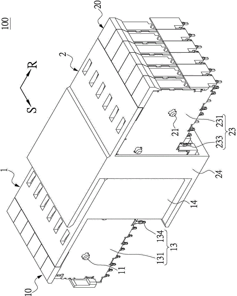
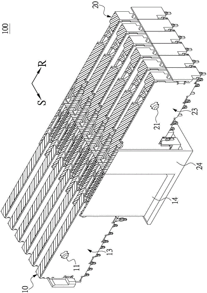
[0055] see Figure 1 to Figure 3 , which is an embodiment of the present invention. What needs to be explained first is that this embodiment corresponds to any position, shape, and relative quantity mentioned in the drawings, and is only used to specifically describe the implementation mode, so as to facilitate understanding of its content. It is not intended to limit the scope of the claims of the present invention.

[0056] The present embodiment is a communication connection device 100 , including a first communication connector 1 and a second communication connector 2 detachably assembled with each other along a plugging direction R. As shown in FIG. For ease of understanding, the following will describe the structures of the first communication connector 1 and the second communication connector 2 respectively, and then introduce the connection relationship between them.

[0057] like Figure 4 and Figure 5 As shown, the first communication connector 1 includes a plura...


PUM


Abstract

Provided are a communication connection device and a lead frame group thereof. The lead frame group of the communication connection device comprises two lead frames which are separately assembled along a plugging direction. Each lead frame comprises an insulating frame, and a plurality of signal terminals and grounding terminals on the insulating frame. One of the two grounding terminals is provided with a shielding sheet and a plurality of groups of elastic arms extending out of the insulating frame, and the other grounding terminal is provided with a shielding portion extending out of the insulating frame. The two grounding terminals are connected with each other on a shielding direction which is vertical to the plugging direction, and the plurality of groups of elastic arms are respectively abutted against the shielding portions. In the space surrounded by extension of the shielding sheet profile along the shielding direction, the shielding direction passes through at least one of the shielding sheets, the plurality of groups of elastic arms, and the shielding portions. Thus, the lead frame group with better shielding effect is provided.

Description

technical field [0001] The invention relates to a connection device, and in particular to a communication connection device suitable for high-frequency signal transmission and a lead frame group thereof. Background technique [0002] Commonly used communication connection devices include two communication connectors that are inserted into each other to achieve the effect of signal transmission. Wherein, each communication connector includes a ground terminal and a signal terminal. When the two communication connectors are inserted into each other along a plugging direction, the signal terminals of the two communication connectors are connected to each other to transmit signals, and the The ground terminals of the above two communication connectors provide a shielding effect so as to prevent the above signals from being interfered during transmission. [0003] However, the grounding terminals of two commonly used communication connectors fail to achieve a comprehensive shiel...

Claims


Application Information

Patent Timeline
Patent Type & Authority Applications(China)
IPC IPC(8): H01R13/6581
CPCH01R13/652H01R13/6581H01R13/6591H01R12/727H01R12/732H01R13/6582H01R12/724H01R13/6587H01R13/648
Inventor 包中南王孝银林钰雄
Owner STARCONN ELECTRONICS SU ZHOU CO LTD
Why Eureka
Try Eureka