

Apparatus and method for detecting colour ring rotation of projection type image display
A technology for image display equipment and rotation detection, which is applied in the direction of cathode ray tube indicators, static indicators, instruments, etc., can solve problems such as projection interference, reduced brightness of projectors, and reduced light use efficiency, so as to improve use efficiency and improve The effect of full brightness, reducing the possibility of heat and interference with the picture
- Summary
- Abstract
- Description
- Claims
- Application Information
AI Technical Summary
Problems solved by technology
Method used
Image

Examples
Embodiment Construction
[0037] Hereinafter, embodiments of the present invention will be described in more detail with reference to the drawings.
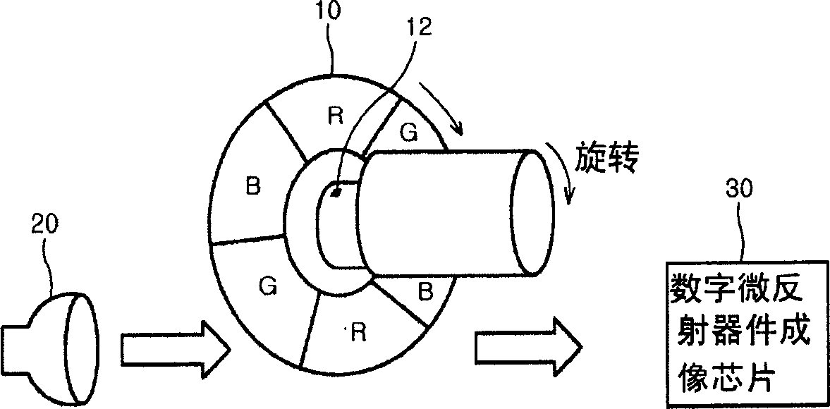
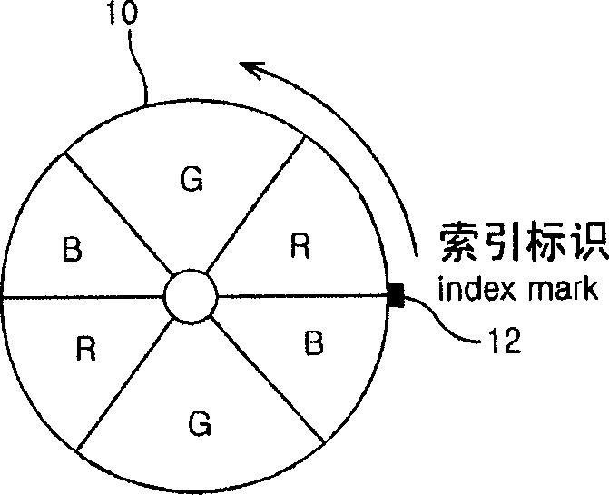
[0038] Figure 2a It is a schematic block diagram of a color ring rotation detection device for a projection-type image display device according to an embodiment of the present invention; Figure 2bis a detailed view of the colored rings.
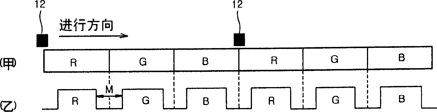
[0039] refer to Figure 2a and Figure 2b It can be seen that the color ring rotation detection device of the projection type image display device is composed of the following parts: the chromaticity filter of the three primary colors of red (R), green (G) and blue (B) arranged in a group of two and A color ring 10 including 6 index marks 12 arranged at a specified position corresponding to the cylindrical part of each chroma filter demarcation line; when the color ring rotates, detect each index mark 12, and output a light detection 14 of the detected signal; A delay time judging section that judges in response to...
PUM
 Abstract
Description
Claims
Application Information