Electrodynamic Actuator

An electric actuator and actuator technology, which is applied to electric components, electromechanical devices, electrical components, etc., can solve the problem of not setting a return element, and achieve the effects of small overall size, high cost performance, and easy implementation.

Active Publication Date: 2015-03-25
BURKERT WERKE
View PDF7 Cites 10 Cited by
  • Summary
  • Abstract
  • Description
  • Claims
  • Application Information

AI Technical Summary

Problems solved by technology

Since the reset process will be obtained by reversing the direction of the current flow, no recovery element is provided

Method used


Image

  • Electrodynamic Actuator
  • Electrodynamic Actuator
  • Electrodynamic Actuator

Examples


Embodiment Construction

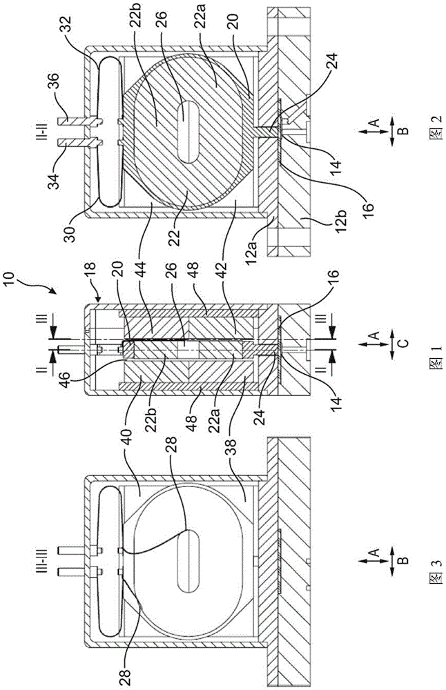
[0088] Figure 1 to Figure 3 A first embodiment of a microvalve 10 with an electric actuator is shown. The electric actuator is mounted on the two-part fluid housings 12a, 12b, and the valve seat 14 is formed in the two-part fluid housings 12a, 12b. A diaphragm 16 clamped between the housing halves 12a and 12b is able to open or close the valve seat 14 by means of an electric actuator.

[0089] The electric actuator includes an actuator housing 18 in which the movable control element and immovable magnet arrangement are housed. The control element is mainly formed by a coil carrier 20 made of non-magnetic material and an air-core coil 22 arranged on the coil carrier 20 . The coil carrier 20 is engaged around the air core coil 22 and mounted so as to be linearly movable in the direction A. As shown in FIG. The extension 24 of the coil carrier 20 protrudes into the recess of the upper half 12 a of the fluid housing and cooperates with the partition 16 .

[0090] The air-core...


PUM


Abstract

An electrodynamic actuator, in particular for a microvalve or a micropump, includes a magnet arrangement for generating a magnetic field and a control element movable relative to the magnet arrangement. The control element includes an energizable air-core coil (22) which is arranged in the magnetic field and firmly coupled to a coil carrier (20) made from a nonmagnetic material.

Description

technical field [0001] The present invention relates to an electric actuator, especially an electric actuator for a micro valve or a micro pump. Background technique [0002] Electromagnetic actuators are often used in fluid valve technology. In most such actuators, an armature made of magnetic material is moved by means of a magnetic field generated by a coil. Especially when it is desired to miniaturize the actuator, the options for a design that saves space on the one hand and provides sufficient magnetic force on the other hand are limited. This is due to the fact that with smaller coils the obtained magnetic field strength is greatly reduced, or in other words, the maximum possible current is limited. [0003] In contrast, the magnetic field strength in an electric drive depends on the volume of the permanent magnet employed in the drive, and a reduction in the volume of the permanent magnet has a greater impact on the field strength achievable in the drive than a red...

Claims


Application Information

Patent Timeline
Patent Type & Authority Applications(China)
IPC IPC(8): H02K33/18H02K33/02F16K31/08
CPCF04B43/043F16K99/0015F16K99/0046F16K2099/0094H02K33/18H02K41/0356F04B19/006F16K99/0042H02K41/0358
Inventor C·瑞特M·富克斯J·德克斯R·施罗德R·沙伊贝C·哈特曼
Owner BURKERT WERKE
Why Eureka
Try Eureka