Stepping motor and timepiece provided with stepping motor

A technology of stepping motors and rotors, which is applied in clocks, electromechanical clocks, instruments, etc., can solve problems such as difficulty in miniaturization

Active Publication Date: 2015-03-25
CASIO COMPUTER CO LTD
View PDF7 Cites 13 Cited by
  • Summary
  • Abstract
  • Description
  • Claims
  • Application Information

AI Technical Summary

Problems solved by technology

Therefore, if the shape of the rotor magnet is too complicated, there is a problem that it is difficult to achieve miniaturization

Method used


Image

  • Stepping motor and timepiece provided with stepping motor
  • Stepping motor and timepiece provided with stepping motor
  • Stepping motor and timepiece provided with stepping motor

Examples


no. 1 approach

[0042] Below, refer to figure 1 Moving to FIG. 9 , a first embodiment of the stepping motor of the present invention will be described.

[0043] The stepping motor of this embodiment is a small motor used to drive, for example, a hand movement mechanism and a date mechanism for moving the hands of a watch, but embodiments to which the stepping motor of the present invention can be applied are not limited thereto.

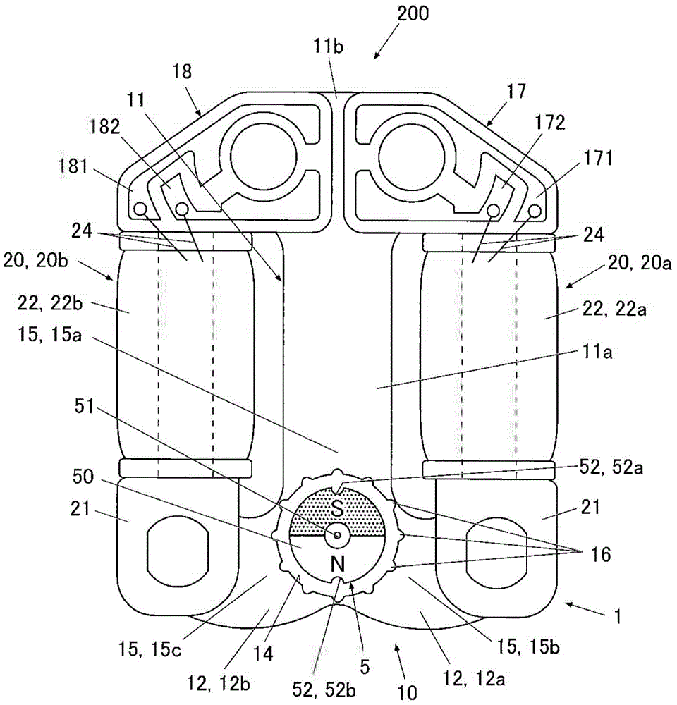
[0044] figure 1 It is a plan view of the stepping motor in this embodiment.

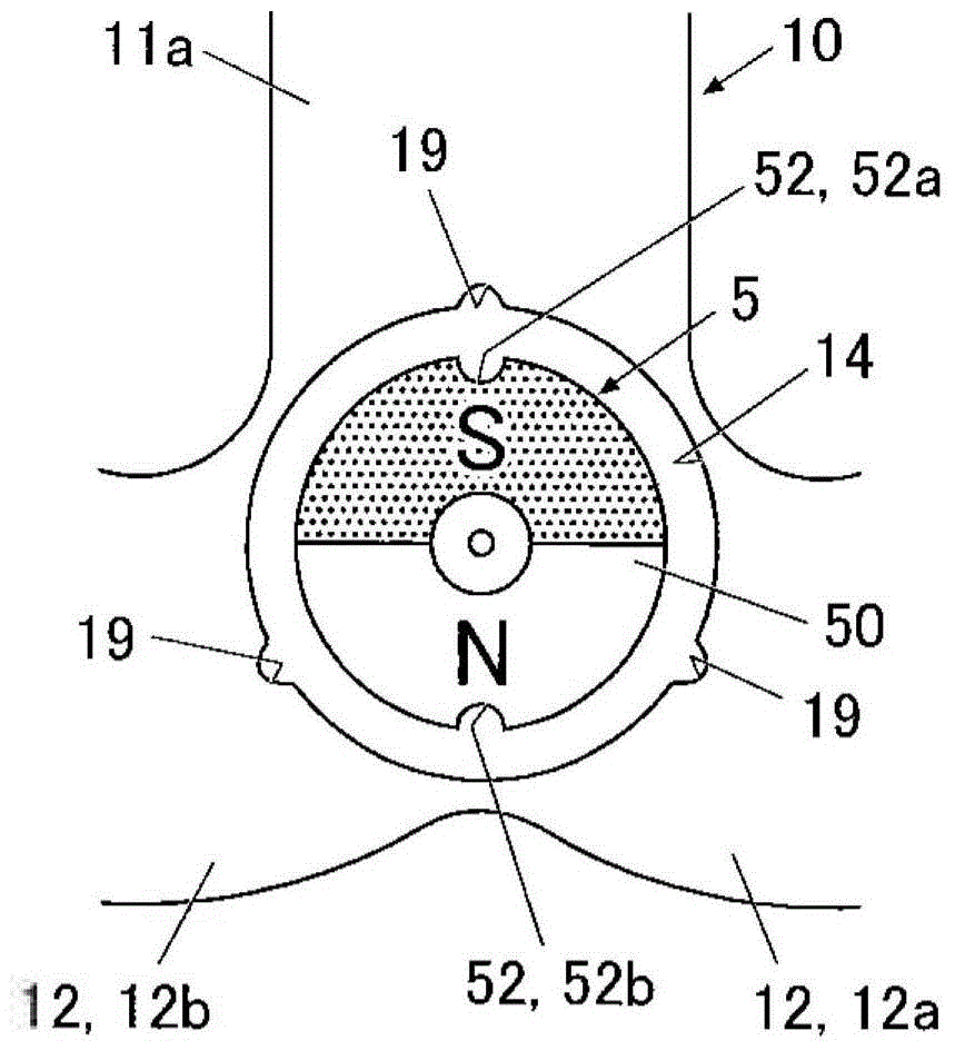
[0045] Such as figure 1 As shown, the stepping motor 200 includes a stator 1 (Stator) and a rotor 5 (Rotor).

[0046] The rotor 5 has a structure in which a rotor magnet 50 magnetized at two poles in the radial direction is attached to a rotation support shaft 51 .

[0047] In this embodiment, the rotor magnet 50 is formed in a substantially cylindrical shape, and the rotation support shaft 51 is attached to the center of the rotor magnet 50 .

[0048] As the rotor magnet 50 , for exa...

no. 2 approach

[0158] Below, refer to Figure 10 , Figure 11A ~ Figure 11D , Figure 12A ~ Figure 12D , Figure 13A ~ Figure 13D , the second embodiment of the stepping motor of the present invention will be described.

[0159] In addition, since the present embodiment differs from the first embodiment in the manner of applying a drive pulse by the drive pulse supply circuit 31 , the differences from the first embodiment in particular will be described below.

[0160] Figure 10 The timing of application of the driving pulse by the driving pulse supply circuit 31 in this embodiment and the application mode (mode) of the driving pulse in each driving pulse application interval are shown.

[0161] like Figure 10 As shown, the drive pulse supply circuit 31 can appropriately change the pulse width applied in each drive pulse application period, and select an application mode (mode) to apply a drive pulse to only one coil 22 in all drive pulse application periods.

[0162] In this manner,...

no. 3 approach

[0200] Next, refer to Figure 14 , Figure 15A ~ Figure 15D , Figure 16A ~ Figure 16D , Figure 17A ~ Figure 17D , the third embodiment of the stepping motor of the present invention will be described.

[0201]In addition, this embodiment differs from the first embodiment and the like in the application method of the drive pulse by the drive pulse supply circuit 31 , and the difference from the first embodiment and the like will be described below in particular.

[0202] Figure 14 The timing of application of the driving pulse by the driving pulse supply circuit 31 in this embodiment and the application mode (mode) of the driving pulse in each driving pulse application interval are shown.

[0203] like Figure 14 As shown, the drive pulse supply circuit 31 can appropriately change the pulse width applied in each drive pulse application period, and select an application mode (mode) for applying a drive pulse to both coils 22 in all drive pulse application periods.

[02...


PUM


Abstract

Disclosed is a stepping motor including a rotor including a cylindrical rotor magnet having an M number of magnetization, M being an even number, in a radial direction, and a stator including a stator body and a coil, the stator body having a rotor accommodating space which accommodates the rotor and an N number of magnetic poles, N being an odd number, disposed along an outer periphery of the rotor, and the coil being magnetically coupled with the stator body. Further including rotor stoppers disposed at every predetermined rotation angle which is smaller than an angle obtained by dividing one rotation by a product of the N and the M and a driving pulse supplying circuit which applies driving pulses to rotate the rotor by the predetermined rotation angle to the coil.

Description

technical field [0001] The present invention relates to a stepping motor and a timepiece equipped with the stepping motor. Background technique [0002] Conventionally, there is known a stepping motor that includes two coils, and is capable of forward and reverse rotation by appropriately applying a drive pulse to the coils. [0003] For example, a stepping motor is disclosed in Patent Document 1 (Japanese Patent No. Hei 5-006440). The stator composition. [0004] In a stepping motor, the rotation torque depends on the peak height of the index torque (holding torque). [0005] Therefore, if the rotation angle (step angle) of one step of the rotor can be made smaller while maintaining a high index torque, sufficient rotation torque can be generated with less current consumption. [0006] However, in the past, it was difficult to generate the target torque (holding torque) for forming three or more static stable positions of the rotor with a circular rotor magnet magnetized...

Claims


Application Information

Patent Timeline
Patent Type & Authority Applications(China)
IPC IPC(8): H02K37/14H02P8/02
CPCG04C3/14H02P8/02H02K37/16H02P8/12
Inventor 齐藤雄太川口洋平
Owner CASIO COMPUTER CO LTD
Why Eureka
Try Eureka