A powder microwave heating device and its application method

A microwave heating device, heating device technology, applied in the direction of microwave heating, etc., can solve the problems of high price, increase the total power of heating equipment, and accelerate the aging of magnetron, and achieve the effect of uniform heating and elimination of cold spots

Active Publication Date: 2016-01-20
王俊
View PDF7 Cites 0 Cited by
  • Summary
  • Abstract
  • Description
  • Claims
  • Application Information

AI Technical Summary

Problems solved by technology

Household microwave ovens are the main application in life, and generally low-power magnetrons can meet the requirements; industrial applications require large heating power. The current solution is: use high-power magnetrons, but due to high-power magnetrons It is very difficult to manufacture the tubes and the price is very expensive; the second is to increase the number of low-power magnetrons to increase the total power of the heating equipment, which also brings new problems: since the microwave sources generated by each magnetron are almost impossible to achieve the same phase, Power accumulation and superposition cannot be effectively achieved. On the contrary, the aging of the magnetron is accelerated due to the mutual irradiation between the magnetrons, and there are many restrictions on the volume and shape of the heating object due to the limited microwave penetration depth.

Method used


Image

  • A powder microwave heating device and its application method

Examples


Embodiment 1

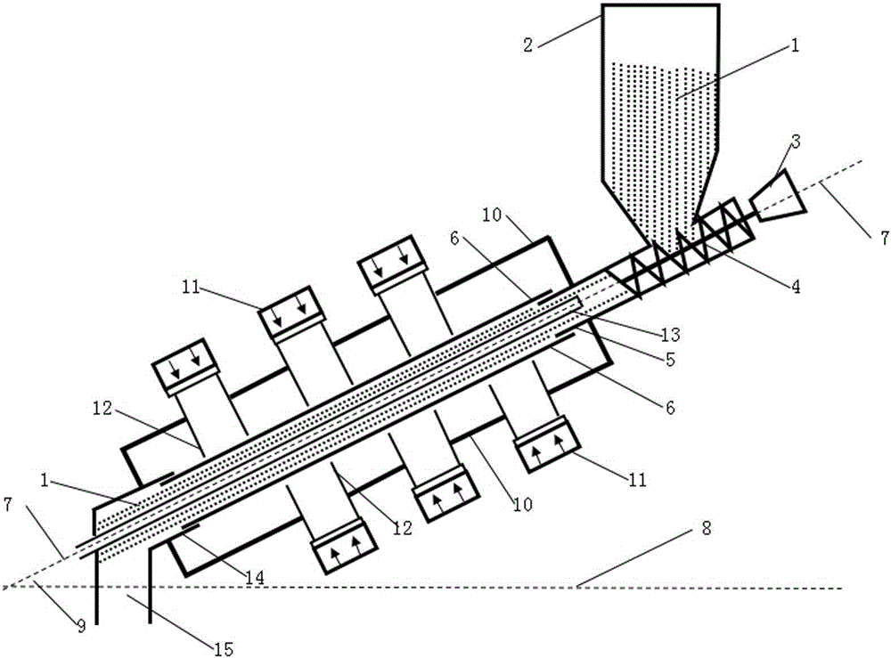
[0050] See figure 1 , crushed to <100 micron powder 1 into the mineral powder silo 2 for standby, control the speed of the motor 3 to make the screw push rod 4 rotate at 50 rpm, and the screw push rod 4 rotates to push the powder 1 through the forming cone sleeve 5 into the inner The equipment inclination angle 9 formed by the centerline 7 of the tube 6 and the heating device and the horizontal plane 8 is close to and not greater than the self-flow angle of the powder 1, and the powder 1 in the inner tube 6 is in a critical state of self-flow; the heating device installed on the outer wall of the outer tube 10 The microwave source 11 divides the inner tube 6 and the outer tube 10 of the heating chamber into six heating sections. Three 1.5KW magnetrons are installed on each heating section, with a total power of 27KW. The opening of the waveguide 12 is close to the outer wall of the inner tube 6 Turn on the power supply of the heating microwave source 11, the microwave that the...

Embodiment 2

[0052] See figure 1 , crushed to <100 micron powder 1 into the mineral powder bin 2 for standby, control the speed of motor 3 to make the screw push rod 4 rotate at 80 rpm, and the screw push rod 4 rotates to push the powder 1 through the forming cone sleeve 5 into the inner The equipment inclination angle 9 formed by the centerline 7 of the tube 6 and the heating device and the horizontal plane 8 is close to and not greater than the self-flow angle of the powder 1, and the powder 1 in the inner tube 6 is in a critical state of self-flow; the heating device installed on the outer wall of the outer tube 10 The microwave source 11 divides the inner tube 6 and the outer tube 10 of the heating chamber into 10 heating sections, and each heating section is equipped with three 1.5KW magnetrons with a total power of 45KW. The opening of the waveguide 12 is close to the outer wall of the inner tube 6 Turn on the power supply of the heating microwave source 11, the microwave that the he...


PUM


Abstract

A powder microwave heating device comprises a spiral pushing device and a heating bin, wherein the heating bin is of a closed tubular structure and composed of an inner pipe (6) and an outer pipe (10); the spiral pushing device comprises a forming conical sleeve (5) of a tubular structure, one end of the forming conical sleeve (5) is closed, a discharging outlet of a powder bin (2) is connected with a feeding inlet in the side wall of the forming conical sleeve (5), a spiral push rod (4) arranged in an inner cavity of the forming conical sleeve is arranged below the feeding inlet in the side wall of the forming conical sleeve, a shaft of the spiral push rod (4) penetrates through the closed end of the forming conical sleeve (5) to be connected with a motor, and the spiral pushing device is formed. The powder microwave heating device is simple in structure, convenient to operate and wide in universality.

Description

technical field [0001] The invention relates to the field of microwave heating of powder, in particular to a microwave heating device for powder and a method for using the same. Background technique [0002] The traditional heating method of powder is to burn fuel, resistance heating, etc. as the heat source. The heat energy obtained by the powder is increased by radiation and conduction heat transfer. The heat transfer and temperature rise of the powder are from the surface to the inside, and the heating is slow and The thermal efficiency is not high, and there is a temperature difference between the core and the surface. [0003] Microwave heating is a microwave source that applies an alternating external electric field to the heating powder. The microwave frequencies used for industrial heating are mainly 915MHz and 2450MHz. The polar molecules in the powder swing at such frequencies within one second to generate heat energy. is huge, the higher the frequency of the appl...

Claims


Application Information

Patent Timeline
Patent Type & Authority Patents(China)
IPC IPC(8): H05B6/80
Inventor 王俊
Owner 王俊
Why Eureka
Try Eureka