LED locating lamp, intelligent lighting system based on LED locating lamps and control method

A technology of intelligent lighting and LED lamp body, applied in the direction of energy-saving control technology, lighting device, electric lamp circuit layout, etc., can solve problems such as misoperation and lighting, and achieve the effect of improving intelligence and improving control anti-interference.

Active Publication Date: 2015-03-25
SHENZHEN MASON TECH
View PDF6 Cites 13 Cited by
  • Summary
  • Abstract
  • Description
  • Claims
  • Application Information

AI Technical Summary

Problems solved by technology

[0002] At present, LED intelligent lighting is still controlled based on traditional sensors, such as PIR pyro-infrared sensors, microwave sensors, or sound and light control methods. Cause misoperation, for example, the sound-activated lights are often turned on due to environmental noise (such as the horn of a car on the road or the alarm of an electric car in a community, etc.)

Method used


Image

  • LED locating lamp, intelligent lighting system based on LED locating lamps and control method
  • LED locating lamp, intelligent lighting system based on LED locating lamps and control method
  • LED locating lamp, intelligent lighting system based on LED locating lamps and control method

Examples


Embodiment 1

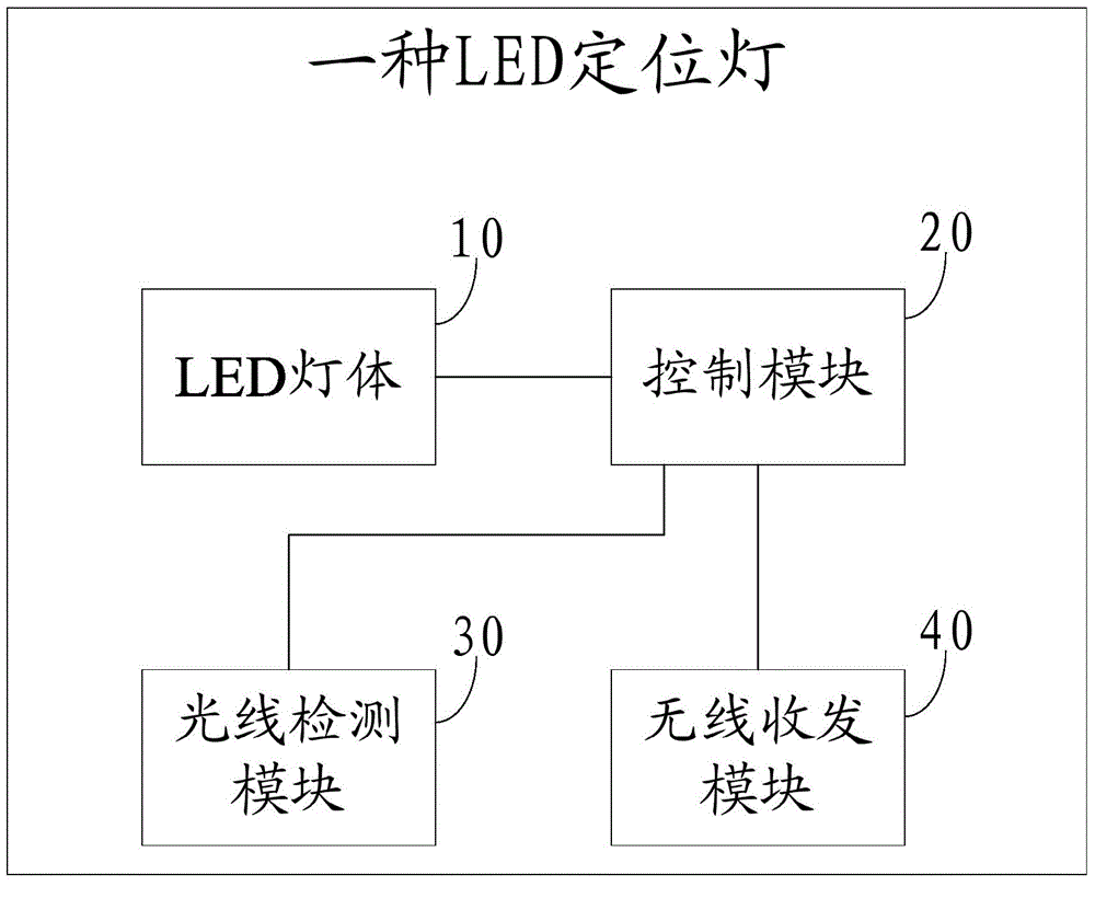
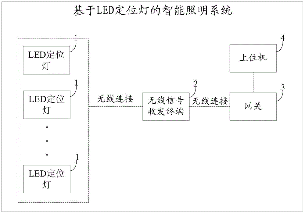
[0059] Embodiment 1 of the present invention is: a control method of a lighting system based on LED positioning lights, wherein the lighting system includes more than three reference lights (that is, LED positioning lights), ZigBee wireless transceiver terminals, a gateway, and a host PC;

[0060] ZigBee wireless transceiver module, EEROM and light detection module are integrated in the reference lamp;

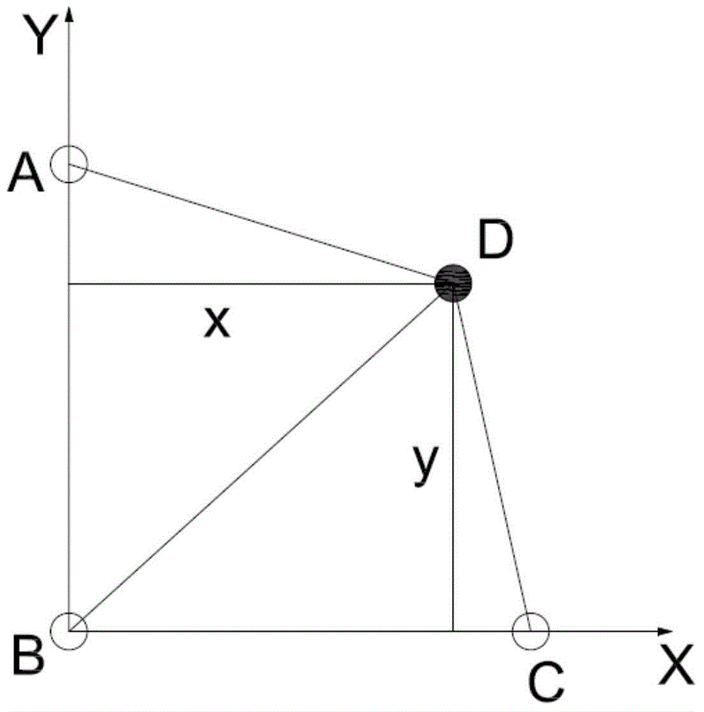
[0061] Please refer to Figure 5 , the workflow of the reference lamp is:

[0062] The reference light receives communication information (ie wireless signal), and judges according to the information;

[0063] If the communication information is a positioning request sent by the positioning target, the acquired RSSI value of the wireless signal and the coordinates of the reference light are sent to the target (that is, the wireless signal transceiver terminal);

[0064] If the communication information is to obtain the position information of the reference light, send the co...


PUM


Abstract

The invention discloses an LED locating lamp. The LED locating lamp is controlled to be turned on and off according to RSSI values of wireless signals transmitted by a wireless signal receiving and transmitting terminal. The invention further discloses an intelligent lighting system based on the LED locating lamps. The intelligent lighting system comprises a gateway, an upper computer, the wireless signal receiving and transmitting terminal and the three or more LED locating lamps. The LED locating lamps calculate the RSSI values of the received wireless signals and transmit the RSSI values and geographic positions to the wireless signal receiving and transmitting terminal. The wireless signal receiving and transmitting terminal calculates the position of the wireless signal receiving and transmitting terminal through the RSSI values and transmits the position to the upper computer. The upper computer calculates a motion track of the wireless signal receiving and transmitting terminal and controls the LED locating lamps on the track to be turned on according to the motion track. The invention further discloses a control method of the intelligent lighting system based on the LED locating lamps.

Description

technical field [0001] The invention relates to the technical field of intelligent lighting, in particular to an LED positioning light, an intelligent lighting system and a control method based on the LED positioning light. Background technique [0002] At present, LED intelligent lighting is still controlled based on traditional sensors, such as PIR pyro-infrared sensors, microwave sensors, or sound and light control methods. Cause misoperation, for example, the sound-activated lights are often turned on due to environmental noise (such as the horn of a car on the road or the alarm of an electric vehicle in a community, etc.). Contents of the invention [0003] The technical problem to be solved by the present invention is to provide a more intelligent and anti-interference LED positioning light and an intelligent lighting system and control method based on the LED positioning light. [0004] In order to solve the above-mentioned technical problems, the technical solutio...

Claims


Application Information

Patent Timeline
Patent Type & Authority Applications(China)
IPC IPC(8): H05B37/02
CPCY02B20/40
Inventor 李志江胡亮谭剑平
Owner SHENZHEN MASON TECH
Why Eureka
Try Eureka