Supercharge Your Innovation With Domain-Expert AI Agents!

Airbag type compression device

A pressing device and air bag technology, applied in the direction of clamping device, positioning device, workpiece clamping device, etc., to achieve the effect of low cost and convenient positioning

Inactive Publication Date: 2015-04-01
重庆市合川区均恒金属加工厂
View PDF0 Cites 19 Cited by
  • Summary
  • Abstract
  • Description
  • Claims
  • Application Information

AI Technical Summary

Problems solved by technology

[0004] The present invention provides an airbag-type clamping device to solve the problem of needing to provide a special driving mechanism or manpower to keep the workpiece clamped continuously

Method used


Image

  • Airbag type compression device

Examples


Embodiment Construction

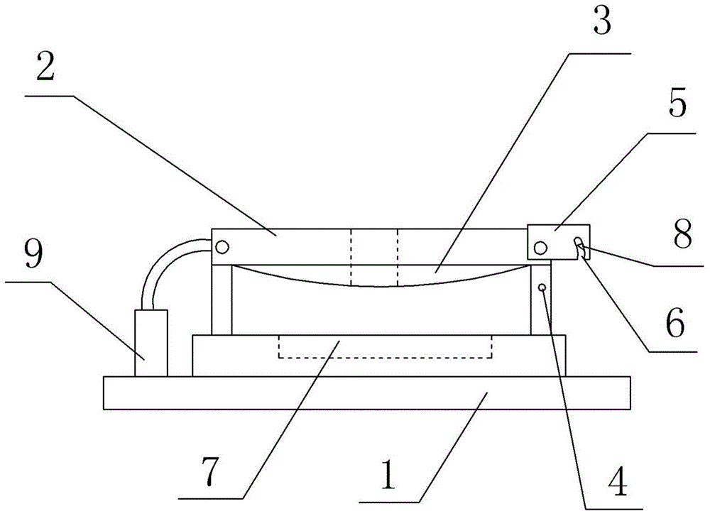
[0013] The reference signs in the accompanying drawings of the description include: base 1 , pressure plate 2 , air bag 3 , round pin 4 , locking plate 5 , groove 6 , positioning groove 7 , blocking piece 8 , and air pump 9 .

[0014] Such as figure 1 As shown, an airbag 3 type pressing device in this embodiment includes a base 1 , a pressing plate 2 arranged on the base 1 , an airbag 3 and a round pin 4 fixed on the base 1 . A space for accommodating workpieces is formed between the base 1 and the pressing plate 2 , and a positioning groove 7 is provided on the upper surface of the base 1 . There is a through hole on the pressing plate 2, the left end of the pressing plate 2 is hinged on the base 1, and the locking plate 5 is hinged on the right end of the pressing plate 2. A groove 6 with an open end is provided on the locking plate 5 , the inner wall of the groove 6 can contact the round pin 4 , a groove is formed on the inner wall of the groove 6 , and a blocking piece 8 ...


PUM


Abstract

The invention discloses an airbag type compression device which comprises a base, a pressing plate, an airbag and a round pin. The pressing plate is arranged on the base, a space for containing a workpiece is formed between the base and the pressing plate, the round pin is fixed on the base, one end of the pressing plate is hinged on the base, a locking plate is hinged at the other end of the pressing plate, a slot is formed in the locking plate, an opening is formed in one end of the slot, the inner wall of the slot can contact with the round pin, a groove is formed in the inner wall of the slot, a retaining piece is arranged in the groove, a pressing spring is arranged between the retaining piece and the groove, one plane of the retaining piece facing the opening of the slot is an inclined plane, the inclined plane is inclined toward the direction far away from the opening of the slot, and the air bag is arranged on one side of the pressing plate facing the workpiece. The air bag is arranged on the pressing plate, different amounts of gas can be inflated into the air bag, so that different workpieces are pressed, different pressing plates do not need to be designed according to different workpieces, the locking plate is arranged on the pressing plate, the pressing plate can be locked through the locking plate, and a special driving device or labor for providing the clamping force is omitted.

Description

technical field [0001] The invention belongs to the technical field of devices for fastening or fixing components or machine parts. Background technique [0002] Before the workpiece is processed, the workpiece needs to be fixed and positioned to prevent the workpiece from moving during processing. The common workpiece clamping mechanism now clamps the workpiece through two opposite jaws, and provides a continuous clamping force to fix the workpiece. [0003] However, the above-mentioned structure has the following disadvantages: the setting of the jaws needs to be designed according to the shape of the workpiece, otherwise the jaws and the workpiece will be in point contact, which will easily damage the workpiece. It is necessary to provide a special driving mechanism or manpower to make the jaws have a continuous clamping force on the workpiece to ensure that the workpiece will not fall from the jaws, but the special driving mechanism and manpower clamping will inevitably...

Claims


Application Information

Patent Timeline
IPC IPC(8): B25B11/00B23Q3/00
CPCB25B11/00B23Q3/08B23Q2703/04
Inventor 张均
Owner 重庆市合川区均恒金属加工厂
Features
  • R&D
  • Intellectual Property
  • Life Sciences
  • Materials
  • Tech Scout
  • Unparalleled Data Quality
  • Higher Quality Content
  • 60% Fewer Hallucinations
Learn More