Locking method of filter cylinder

A filter cylinder and tool body technology, applied in hand-held tools, manufacturing tools, etc., can solve the problems of limited space, inconvenient operation, laborious and other problems, and achieve the effect of convenient locking and simple structure

Active Publication Date: 2016-04-27
CHONGQING EVER YOUNG ENTERPRISES DEV
View PDF8 Cites 0 Cited by
  • Summary
  • Abstract
  • Description
  • Claims
  • Application Information

AI Technical Summary

Problems solved by technology

[0003] The biggest defect of the above-mentioned locking method is: if the distance between multiple filter cylinders is relatively close, then the space is relatively limited. Tight, there are also defects of inconvenient and laborious operation, so it is urgent to solve the above technical problems

Method used


Image

  • Locking method of filter cylinder
  • Locking method of filter cylinder
  • Locking method of filter cylinder

Examples


Embodiment Construction

[0018] Below in conjunction with accompanying drawing and embodiment the present invention will be further described:

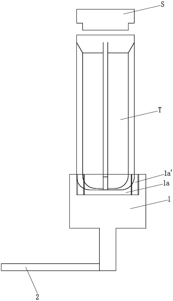
[0019] like figure 1 , 2 And shown in 3, a kind of locking method of filter core cylinder is characterized in that comprising the following steps:

[0020] Step a: first fix the upper cover S, and initially screw the upper cover S and the filter element cylinder T together;

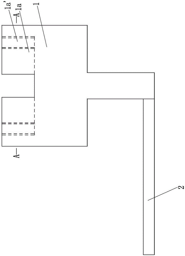
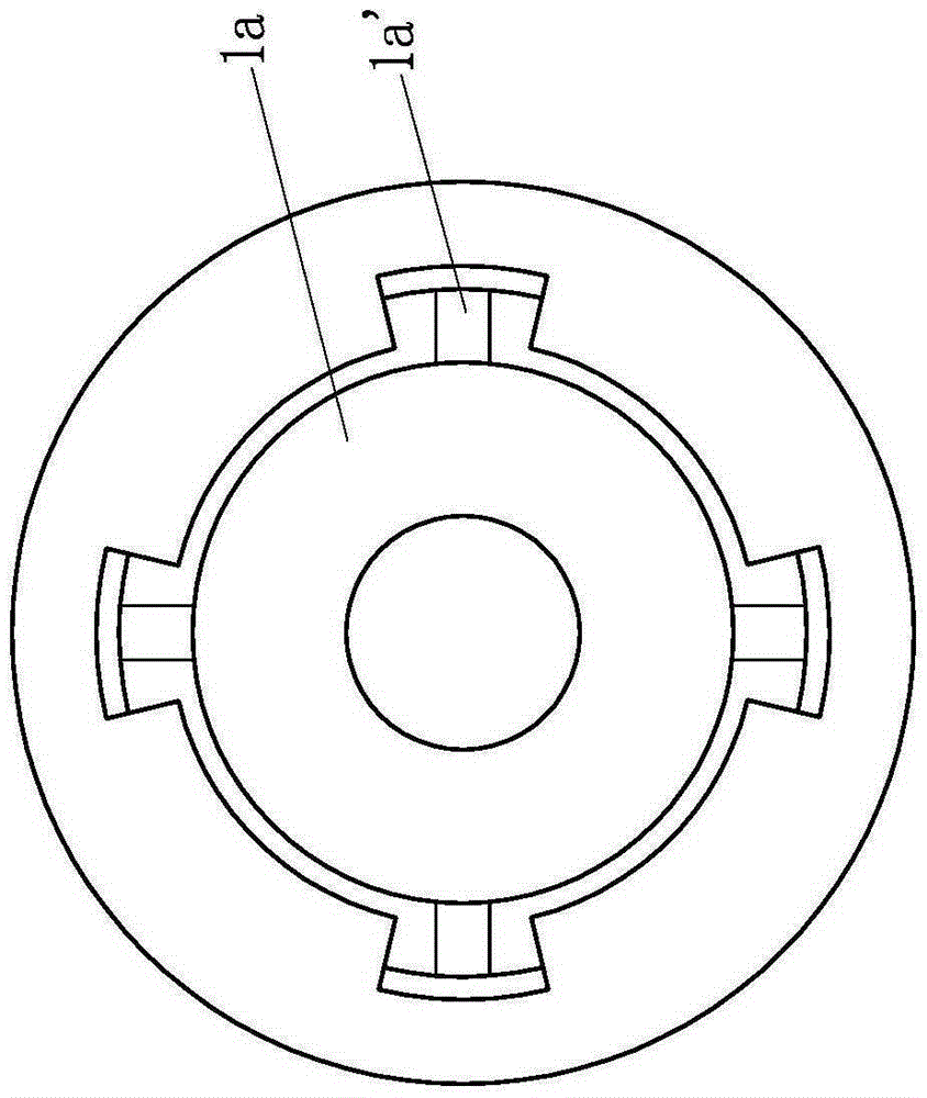
[0021] Step b: Select a locking tool of corresponding size and specification. The locking tool is composed of a tool body 1 and a rotating rod 2. The tool body 1 is a two-stage stepped shaft structure with a large upper part and a smaller lower part. The bottom surface of the small diameter part A described rotating rod 2 is fixedly arranged, and this rotating rod is perpendicular to the axis line of the tool body 1; the distance from the top surface of the rotating rod 2 to the top surface of the tool body 1 is 7-10mm, and can be further preferably 8, 9, 10mm, and the length of the r...


PUM


Abstract

The invention discloses a filter element cartridge locking method. The filter element cartridge locking method is characterized by comprising the following steps: step a, an upper cover is fixed at first and then in preliminary threaded connection with the filter element cartridge; step b, a locking tool of a corresponding size is selected and a rotating rod is fixedly arranged on the bottom surface of the small-diameter section of the tool body of the locking tool; a circular groove is formed in the top surface of the large-diameter section of the tool body; 2-5 limiting pits are formed in the wall of the circular groove in the peripheral direction; step c, the circular groove of the tool body sleeves the bottom of the filter element cartridge; the limiting pits in the wall of the circular groove are in tight fit with reinforcing ribs on the outer wall of the filter element cartridge, and finally, the suspended section of the rotating rod is held by a hand and rotated; step d, after locking, the locking tool is taken down. As the distance between the top surface of the rotating rod and the top surface of the tool body is 7-10mm and the length of the rotating rod is 8-15mm, an enough space is formed to rotate the rotating rod to lock the filter element cartridge, and therefore, the defect of a traditional method failing in locking the filter element cartridge due to the limited space can be effectively overcome.

Description

technical field [0001] The invention belongs to the field of locking a filter element cylinder, and in particular relates to a locking method for a filter element cylinder. Background technique [0002] After the filter element is installed into the filter element cylinder, the filter element cylinder and the upper cover need to be locked together. At present, a belt or a plastic wrench is usually set in the middle of the filter cylinder. The belt or plastic wrench is in close contact with the reinforcement ribs outside the filter cylinder, and then the filter cylinder is rotated by rotating the belt or plastic wrench, so that the filter cylinder The body and the upper cover are locked. [0003] The biggest defect of the above-mentioned locking method is: if the distance between multiple filter cylinders is relatively close, then the space is relatively limited. Tight, also there is the defective of inconvenient operation, laborious, be badly in need of solving above-menti...

Claims


Application Information

Patent Timeline
Patent Type & Authority Patents(China)
IPC IPC(8): B25B27/14
CPCB25B27/143
Inventor 林莹陈
Owner CHONGQING EVER YOUNG ENTERPRISES DEV
Why Eureka
Try Eureka