Cylinder locking method

A cylinder and locking column technology, applied in separation methods, chemical instruments and methods, filtration and separation, etc., can solve the problems of limited space, labor, inconvenient operation, etc., and achieve simple structure, low labor intensity, and convenient locking. Effect

Active Publication Date: 2016-03-23
CHONGQING EVER YOUNG ENTERPRISES DEV
View PDF13 Cites 0 Cited by
  • Summary
  • Abstract
  • Description
  • Claims
  • Application Information

AI Technical Summary

Problems solved by technology

[0003] The biggest defect of the above-mentioned locking method is: if the distance between multiple filter cylinders is relatively close, then the space is relatively limited. Tight, there are also defects of inconvenient and laborious operation, so it is urgent to solve the above technical problems

Method used


Image

  • Cylinder locking method
  • Cylinder locking method
  • Cylinder locking method

Examples


Embodiment Construction

[0017] Below in conjunction with accompanying drawing and embodiment the present invention will be further described:

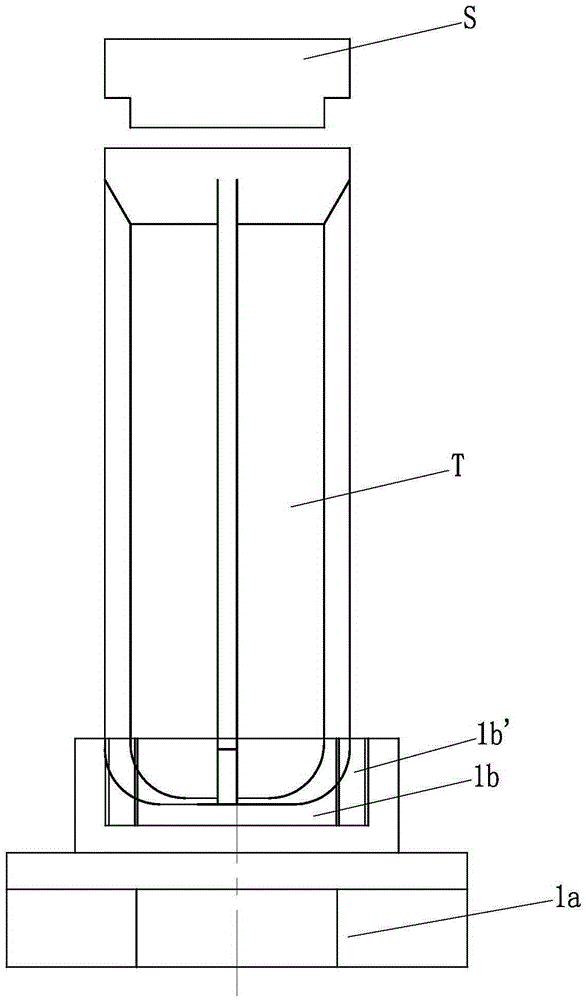
[0018] Such as figure 1 , 2 And shown in 3, a cylinder locking method is characterized in that comprising the following steps:

[0019] Step a: first fix the upper cover S, and initially screw the upper cover S and the filter element cylinder T together;

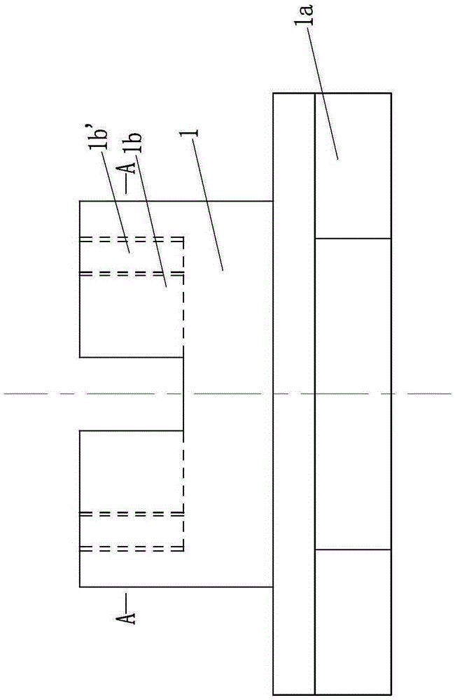
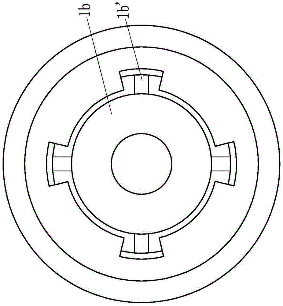
[0020] Step b: Select a locking column of corresponding size and specification. The body 1 of the locking column is made of iron or stainless steel. The part is a regular hexagonal flat part 1a, and the height of the regular hexagonal flat part is 3-5mm. The number of the limiting pits 1b' is four, and the depth of the limiting pits 1b' is 0.5-1.5mm. The center of the top surface of the large-diameter section of the body 1 is provided with a circular groove 1b, and 2-5 limit pits 1b' are evenly distributed on the groove wall of the circular groove along the circumferential direction. These limit pits 1b...


PUM

PropertyMeasurementUnit
heightaaaaaaaaaa
depthaaaaaaaaaa

Abstract

The invention discloses a cylinder locking method. The cylinder locking method is characterized by comprising the following steps: (a) an upper cover is fixed, and is in primary threaded connection with a filter element cylinder; (b) a locking column is selected; a main body of a locking piece is an iron piece or a stainless steel piece, and is a two-section type step shaft structure with small top and large bottom; the lower end of the large-diameter section is a regular hexagonal flat square part; a circular groove is formed in the center of the top surface of the large-diameter section of the main body; and a limiting pit is formed in the groove wall of the circular groove; and (c) the circular groove of the main body coats the bottom of the filter element cylinder; the limiting pit in the groove wall of the circular groove is tightly combined with a reinforcing rib on the outer wall of the filter element cylinder; and a pneumatic sleeve spanner is started to drive the locking column to rotate so as to lock the filter element cylinder. As the pneumatic sleeve spanner fitting the regular hexagonal flat square part is positioned below the filter element cylinder, the defect of incapability of locking the filter element cylinder due to space limitation in a traditional mode can be effectively overcome.

Description

technical field [0001] The invention belongs to the field of installation of filter core cylinders, and in particular relates to a cylinder locking method. Background technique [0002] After the filter element is installed in the filter element cylinder, the filter element cylinder and the upper cover need to be locked together. At present, a belt or a plastic wrench is usually set in the middle of the filter cylinder. The belt or plastic wrench is in close contact with the reinforcement ribs outside the filter cylinder, and then the filter cylinder is rotated by rotating the belt or plastic wrench, so that the filter cylinder The body and the upper cover are locked. [0003] The biggest defect of the above-mentioned locking method is: if the distance between multiple filter cylinders is relatively close, then the space is relatively limited. Tight, also there is the defective of inconvenient operation, laborious, be badly in need of solving above-mentioned technical prob...

Claims


Application Information

Patent Timeline
Patent Type & Authority Patents(China)
IPC IPC(8): B25B27/14B23P19/04
CPCB01D35/30B25B27/14
Inventor 林莹陈
Owner CHONGQING EVER YOUNG ENTERPRISES DEV
Why Eureka
Try Eureka