Compound milling cutter

A technology of milling cutter and cutter head, which is applied in the field of compound milling cutters, can solve the problems of easy burrs on cutting edges, low surface roughness of grooves, and increased production costs, etc., to achieve convenient and quick disassembly, facilitate discharge, and ensure smoothness degree of effect

Inactive Publication Date: 2015-04-01
CHANGZHOU YUJIA PACKAGING
View PDF0 Cites 2 Cited by
  • Summary
  • Abstract
  • Description
  • Claims
  • Application Information

AI Technical Summary

Problems solved by technology

[0002] In the prior art, milling cutters are usually used to process the grooves of materials such as density boards, particle boards, and raw wood; After wear and tear, only a new milling cutter can be replaced, which increases the production cost; when milling, burrs are easily generated on the top and bottom of the cutting edge, resulting in low surface roughness of the groove

Method used


Image

  • Compound milling cutter

Examples


Embodiment 1

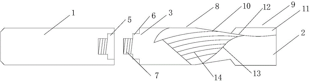
[0014] see figure 1 As shown, the compound milling cutter includes a cylindrical handle 1 and a cutter head part connected to the handle; the cutter head part includes a conical cutter head 2 and a cylindrical connection part 3 affixed to the cutter head The center of the end surface of the handle near the connection part is provided with a groove 4, and the center of the bottom surface of the groove is provided with a screw hole 5; the center of the end surface of the connection part near the connection part is provided with a boss 6 matching the groove , the center of the boss is provided with a screw 7 used in conjunction with the screw hole; the cutter head includes a first cutting portion 8 connected to the connecting portion, a second cutting portion 9 connected to the first cutting portion; the first cutting portion Two helical first cutting edges 10 are arranged on the conical surface; two vertical second cutting edges 11 are oppositely arranged on the conical surface ...

Embodiment 2

[0017] On the basis of Embodiment 1, several fine threads 14 are evenly distributed on the outer surface of the first cutting edge in the same helical direction as the first cutting edge. Since the outer surface of the first cutting edge adopts fine thread, the rigidity of the tool is increased, and it is good to increase the cutting force when processing solid wood or high-density board.

Embodiment 3

[0019] On the basis of Embodiment 1, an arc transition is adopted between the end of the second cutting edge close to the connecting portion and the second cutting portion. Since the second cutting edge is the main cutting edge, the force is relatively large during milling; while the end of the second cutting edge close to the connecting part and the second cutting part adopt a circular arc transition, and there is a support for the second cutting edge Function, can effectively enhance the strength of the second cutting edge.


PUM


Abstract

The invention relates to the technical field of mechanical cutters, and in particular relates to a compound milling cutter. The compound milling cutter comprises a cylindrical handle, and a cutter bit part connected with the handle; the cutter bit part comprises a conical cutter bit, and a cylindrical connecting part fixedly connected with the cutter bit; a concave groove is formed in the center of the end surface of the handle, closing to the connecting part; a screw hole is formed in the center of the bottom surface of the concave groove; a boss in match with the concave groove is arranged in the center of the end surface of one end of the connecting part, close to the handle; a screw used in match with the screw hole is arranged in the center of the boss; the cutter bit comprises a first cutting part connected with the connecting part, and a second cutting part connected with the first cutting part; two spiral first cutting edges are arranged on the conical surface of the first cutting part; two vertical second cutting edges are symmetrically arranged on the conical surface of the second cutting part; a circular arc surface is formed in the part in which the second cutting edge is connected with the conical surface of the second cutting part; the circular arc surface is connected with the bottom of a slag groove. The compound milling cutter has the advantages that the production cost is decreased, and the surface roughness is improved.

Description

technical field [0001] The invention relates to the technical field of mechanical cutters, in particular to a compound milling cutter. Background technique [0002] In the prior art, milling cutters are usually used to process the grooves of materials such as density boards, particle boards, and raw wood; After wear and tear, only a new milling cutter can be replaced, which increases the production cost; during milling, burrs are easily generated on the top and bottom of the cutting edge, resulting in low surface roughness of the groove. Contents of the invention [0003] The purpose of the present invention is to provide a compound milling cutter which reduces production cost and improves surface roughness. [0004] Technical scheme of the present invention is as follows: [0005] The compound milling cutter comprises a cylindrical handle and a cutter head part connected by the handle; the cutter head part includes a conical cutter head and a connecting part of a cylind...

Claims


Application Information

Patent Timeline
IPC IPC(8): B27G13/14
CPCB27G13/14
Inventor 沈园园
Owner CHANGZHOU YUJIA PACKAGING
Why Eureka
Try Eureka