
A reciprocating chain drive mechanism

A driving mechanism and chain technology, applied in conveyors, mechanical conveyors, transportation and packaging, etc., can solve problems such as increasing the labor intensity of employees, and achieve the effects of small occupied space, short transmission lines and simple structure

Active Publication Date: 2016-11-02
XUZHOU CONSTR MACHINERY
View PDF7 Cites 0 Cited by
  • Summary
  • Abstract
  • Description
  • Claims
  • Application Information

AI Technical Summary

Problems solved by technology

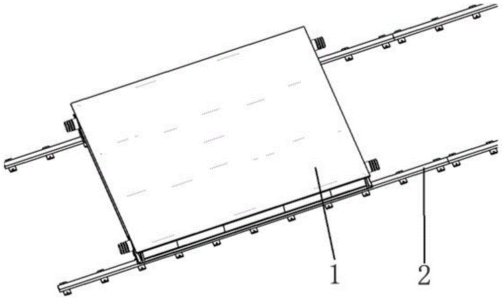
Since the craft car 1 is manually driven, the labor intensity of the employees is increased

Method used


Image

  • A reciprocating chain drive mechanism
  • A reciprocating chain drive mechanism
  • A reciprocating chain drive mechanism

Examples


Embodiment Construction

[0021] The present invention will be further described below in conjunction with accompanying drawing.

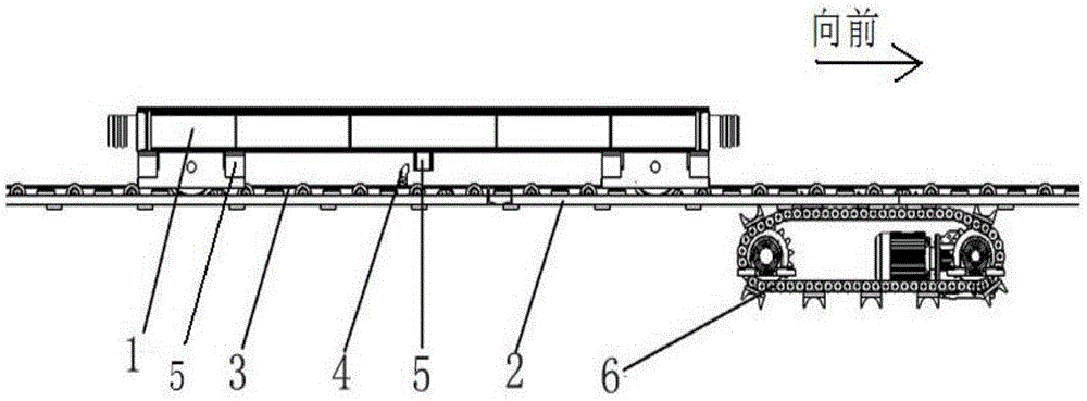
[0022] The direction of the arrow in the figure is moving forward, and the opposite direction is moving backward.

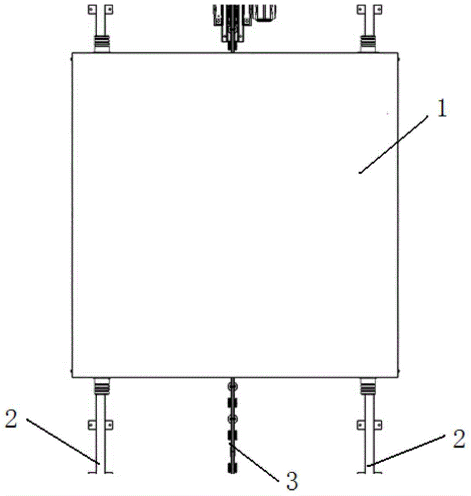
[0023] Such as figure 2 and image 3 As shown, a reciprocating chain drive mechanism of the present invention includes a push rod 3, a push head 4 and a drive device 6, the push rod 3 slides inside the slideway 12, and the drive device 6 is installed at the bottom of the push rod 3, and is connected with The slideway 12 is adjacent, and the driving device 6 converts the positive and negative rotation of the motor into the forward and backward movement of the push rod 3. When the push head 4 connected with the push rod 3 moves forward with the push rod 3, the push head 4 and the process The stopper 5 on the car 1 contacts to drive the craft car 1 to move forward; when the pusher 4 on the push rod 3 moves backward with the pusher 3, the pusher 4 touches the n...


PUM


Abstract

The invention discloses a reciprocating chain drive mechanism, which comprises a push rod (3) and a push head (4) connected with the push rod. The push rod slides in a slideway (12), and also includes a The driving device (6), the driving device is adjacent to the slideway, and the driving device rotates regularly to drive the push rod to reciprocate back and forth. When the push head on the push rod moves forward with the push rod, the push head and the process The contact of the block on the car drives the craft car to move forward; when the push head on the push rod moves backward with the push rod, the push head touches the next stop, and the push head crosses the stop and automatically resets, so as to repeatedly realize the craft car Intermittent forward movement. The present invention adopts the driving device to convert the positive and negative rotation of the motor into the forward and backward movement of the push rod, and then realizes the linear intermittent forward movement of the craft car through the action of pushing the head on the push rod; Short, less transmission parts, no need to mine a large foundation to meet the rotation, occupying a small space, and simple structure.

Description

technical field [0001] The invention relates to a driving mechanism, in particular to a reciprocating chain driving mechanism, which belongs to the technical field of driving devices for assembly lines. Background technique [0002] The automation devices required for assembly line assembly take up a lot of space and require a lot of site coordination, especially for assembly line devices with large structural parts, which often require a large foundation on the ground to realize the function of assembly line operations. Since the assembly line operation needs to continuously move the process vehicle (or loaded workpiece) to the rear station, the existing driving device mostly adopts the form of continuous driving roller chain, which requires mining a large foundation to meet the cycle of the driving device, occupying The larger the site, the higher the cost. [0003] At present, most of the solutions to the problem of large space occupied by assembly line driving devices a...

Claims


Application Information

Patent Timeline
Patent Type & Authority Patents(China)
IPC IPC(8): B65G35/00
Inventor 王建军王厚贞刘涛褚沛
Owner XUZHOU CONSTR MACHINERY
Learn More