Device of utilisation of waste gases for automobile engine

A technology for automobile engines and power transmission devices, which is applied to exhaust devices, engine components, combustion engines, etc., can solve the problems of long power transmission lines, low transmission accuracy, and many intermediate links, and achieve fewer intermediate links and more efficient transmission routes. Short, dynamic effect

Inactive Publication Date: 2010-01-20
CHERY AUTOMOBILE CO LTD
View PDF4 Cites 0 Cited by
  • Summary
  • Abstract
  • Description
  • Claims
  • Application Information

AI Technical Summary

Problems solved by technology

[0004] The problem to be solved by the present invention is that in the process of using exhaust gas energy, due to the use of many parts, long power transmission lines, complex structures, and many intermediate links, the technical problems of poor reliability of the entire system and low transmission accuracy are caused. Provided is an exhaust gas utilization device of an automobile engine

Method used


Image

  • Device of utilisation of waste gases for automobile engine
  • Device of utilisation of waste gases for automobile engine

Examples


Embodiment Construction

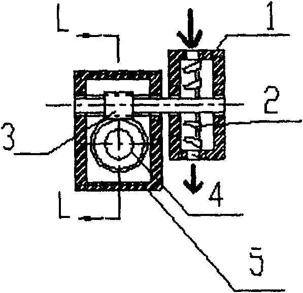
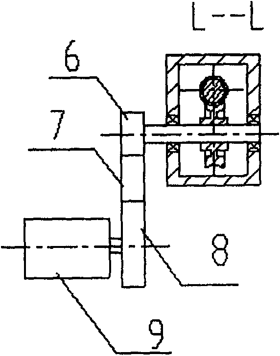
[0017] Such as Figure 1-2 As shown, the exhaust gas utilization device of an automobile engine provided by the present invention is installed at the rear end of the engine exhaust pipe, and the exhaust gas discharged from the engine is used to push the inner blade 2 of the volute 1 to rotate, thereby driving the worm 3 to rotate, and using the worm gear 4. The worm 3 speed reducer converts the waste gas energy into kinetic energy output, uses the pulley and the 4PK belt 7 to drive the generator 9 to work, and provides energy for the starting of the engine and the lighting device of the car.

[0018] The worm wheel 4 and the worm 3 are arranged perpendicular to each other. On the one hand, the power can be effectively transmitted, so that the lateral motion generated by the blade 2 through the splined shaft can be converted into a vertical motion that is convenient for transmission; on the other hand, during the power transmission process , to play the role of deceleration, so...


PUM


Abstract

A utilization device of waste gas from engine on automobile consists of volute, blade set in volute, power transmission unit and speed reduction unit. It is featured as setting power transmission unit and speed reduction unit to be a unified unit and erecting said unified unit between volute and generator.

Description

technical field [0001] The invention belongs to the field of automobile engine accessory manufacturing, and in particular relates to an exhaust gas utilization device of an automobile engine. Background technique [0002] Traditionally, there are two ways to deal with the energy in the exhaust gas of automobile engines. One is to use the exhaust muffler (the muffler is generally composed of intake pipe, exhaust pipe, diffuser pipe, intermediate pipe, partition, outer shell and other components) to consume the exhaust gas. The energy in the exhaust gas is used to prevent the exhaust gas from being directly discharged into the atmosphere to produce strong exhaust noise; the second is to use the exhaust gas turbocharging technology and device to use part of the energy in the exhaust gas to increase the intake pressure of the engine and increase the air charge to improve the power of the engine. sex and economy. But above-mentioned two kinds of treatment methods waste the waste...

Claims


Application Information

Patent Timeline
Patent Type & Authority Patents(China)
IPC IPC(8): F01N5/04
CPCY02T10/16Y02T10/12
Inventor 冯武堂朱航汪久高李力
Owner CHERY AUTOMOBILE CO LTD
Why Eureka
Try Eureka