Automobile door

A technology for car doors and car doors, which is applied in the field of auto parts, can solve problems such as being unable to satisfy people, and achieve good guiding effects, low cost, and simple structure

Inactive Publication Date: 2015-04-01
JIAXING VOCATIONAL TECHN COLLEGE
View PDF5 Cites 1 Cited by
  • Summary
  • Abstract
  • Description
  • Claims
  • Application Information

AI Technical Summary

Problems solved by technology

[0004] But in summer or when the weather is hot, the heat dissipation effect cannot meet people's needs just by opening the windows.

Method used


Image

  • Automobile door
  • Automobile door
  • Automobile door

Examples


Embodiment 1

[0049] The automobile door is hinged on the vehicle body when in normal use, and is used to open or close the entrance of the vehicle body to facilitate users to enter or come out from the vehicle body.

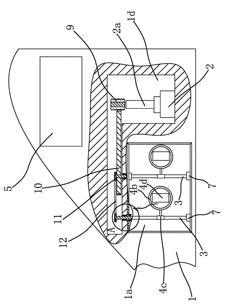
[0050] like figure 1 Shown, this car door comprises car door body 1, motor 2, some rotating shafts 3, some sealing plates 4, vehicle window 5 etc. are formed. Wherein, the vehicle window 5 is arranged on the vehicle door body 1 , and the number of the rotating shafts 3 is the same as that of the sealing plate 4 and is provided in one-to-one correspondence.

[0051] Wherein, a square groove 1a is provided on the outer wall of the door body 1 , and the groove 1a is located below the window 5 . The groove 1a includes 4 inner side walls and a bottom wall, and the 4 inner side walls and the bottom wall are all plane. The joints between the four inner sidewalls and the door body 1 are respectively provided with chamfers to increase the aesthetics of the door.

[0052] The bottom...

Embodiment 2

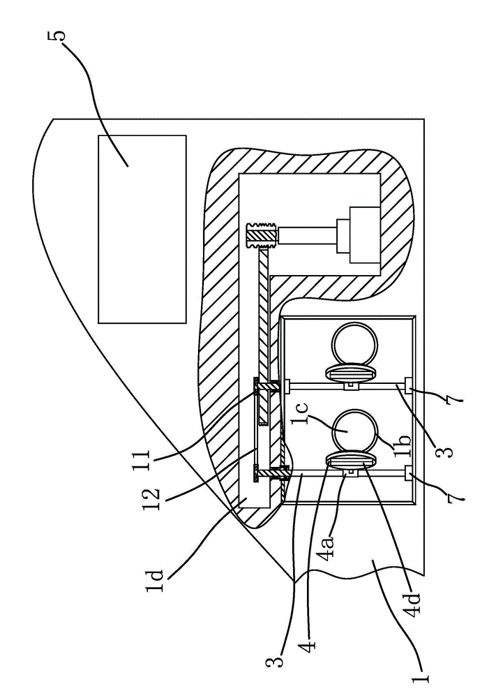
[0073] The structure and principle of the second embodiment are basically the same as that of the first embodiment, except that the outer edge of the connecting part 4a has an annular groove coaxial with it, and the sealing structure includes an O-shaped sealing ring located in the annular groove , when the sealing plate 4 seals the air outlet 1c, the outer peripheral surface of the O-ring is against the inner edge of the connecting cylinder 1b. When the air outlet 1c needs to be closed, the motor 2 is started, so that the sealing plate 4 rotates around the rotating shaft 3, so that the O-shaped sealing ring is against the inner edge of the connecting cylinder 1b, so that the connection between the sealing plate 4 and the air outlet 1c is always kept sealed , that is, all the air outlet holes 1c are in a sealed state, preventing impurities such as water and dust from flowing into the interior of the vehicle body through the gap between the sealing plate 4 and the air outlet hol...

Embodiment 3

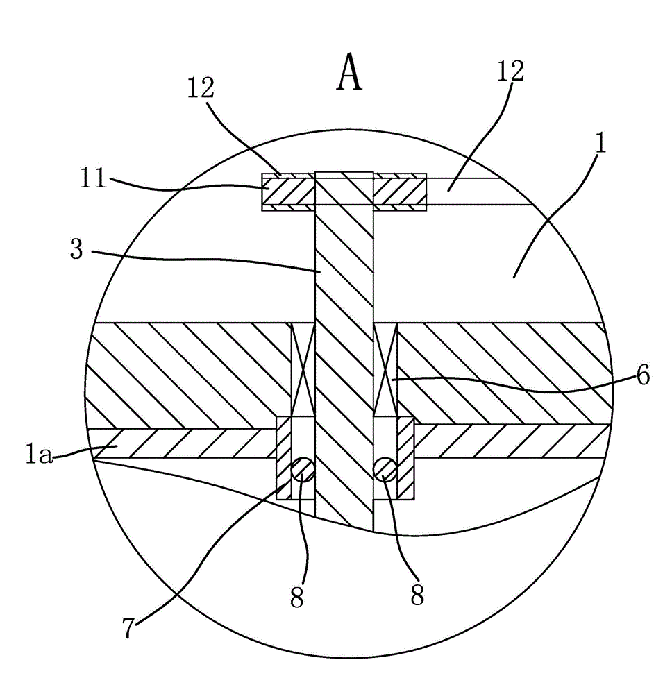
[0075]The structure and principle of the present embodiment three are basically the same as those of the first embodiment, except that the output shaft of the motor 2 is connected with the end of one of the rotating shafts 3, and each end of the rotating shaft 3 is connected with a synchronous wheel 11, and several synchronous The wheels 11 are connected by a timing belt 12 . The purpose of the present invention can also be achieved by directly driving one of the rotating shafts 3 to rotate through the motor 2 so as to drive the other rotating shafts 3 to rotate synchronously through the synchronous belt 12 .


PUM


Abstract

The invention provides an automobile door and belongs to the technical field of automobile parts. The automobile door solves the problem of poor heat dissipating performance of existing automobile doors. The automobile door comprises an automobile door body hinged to an automobile body, and the outer wall of the automobile door body is provided with a groove; a plurality of rotating shafts are axially fixed inside the groove, and the bottom wall of the groove is provided with air holes identical to the rotating shafts in number; the plurality of rotating shafts are fixedly provided with sealing plates respectively; a motor is arranged inside the automobile door body and can drives the plurality of rotating shafts to rotate simultaneously; under the action of the motor, every sealing plate can seal the corresponding air hole, and a sealing structure is arranged between every sealing plate and the corresponding air holes for sealing the connection of the sealing plate and the air holes. The automobile door has the advantages of being high in heat dissipating effects.

Description

technical field [0001] The invention belongs to the technical field of automobile parts and relates to an automobile door. Background technique [0002] With the continuous development of the automobile industry and the continuous improvement of people's material living standards, the automobile industry has experienced hundreds of years of development, and various new technologies continue to emerge, and people's desire to buy cars is getting higher and higher. [0003] Existing automobile generally comprises compositions such as vehicle body, car door, and wherein, car door is hinged on the vehicle body. Existing cars basically dissipate heat through the air conditioner located inside the body or through the windows installed on the doors, but when considering environmental protection factors, existing cars can only dissipate heat by opening the windows . [0004] But when summer or weather is hot, only by opening the car window for cooling effect can not meet people's n...

Claims


Application Information

Patent Timeline
Patent Type & Authority Applications(China)
IPC IPC(8): E06B3/70B60H1/24
Inventor 吕灵巧
Owner JIAXING VOCATIONAL TECHN COLLEGE
Why Eureka
Try Eureka