Sliding sleeve structure for permanent completion and application method thereof

A sliding sleeve, permanent technology, applied in earthwork drilling, wellbore/well components, wellbore/well valve devices, etc., can solve the problem that the sliding sleeve cannot be selectively closed, oil and gas cannot be produced normally, and oil and gas production is affected To achieve the effect of improving oil and gas recovery, avoiding mis-opening and mis-closing, and convenient operation

Active Publication Date: 2015-04-01
BC P INC CHINA NAT PETROLEUM CORP +1
View PDF4 Cites 1 Cited by
  • Summary
  • Abstract
  • Description
  • Claims
  • Application Information

AI Technical Summary

Problems solved by technology

[0004] These two kinds of sliding sleeves have their own advantages, but they also have their own shortcomings: the self-locking sliding sleeves cannot be closed selectively, and when the reservoir produces a large amount of water, sometimes it will affect the oil and gas production of other reservoirs , or even drown the entire oil and gas well; although the non-self-locking sliding sleeve can be selectively closed, after the sliding sleeve is opened, the movable sliding sleeve can slide freely. The passage of the column caused the sliding sleeve to be closed by mistake, resulting in the failure of normal production of oil and gas

Method used


Image

  • Sliding sleeve structure for permanent completion and application method thereof
  • Sliding sleeve structure for permanent completion and application method thereof

Examples


Embodiment 1

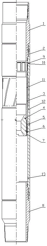
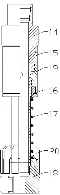
[0027] A sliding sleeve structure for permanent well completion, comprising an upper joint 1, a body 2, a movable sliding sleeve 3, an easy-drilling ball seat 4, a lower joint 8 and a self-locking mechanism, and the upper joint 1 and the lower joint 8 are respectively fixedly connected to The upper and lower ends of the body 2, the body 2 is provided with an injection groove, the movable sliding sleeve 3 is located in the body 2 to close the injection groove, and is connected to the body 2 through a pin 5, and the upper end of the movable sliding sleeve 3 is provided with a claw hook 9 , the inner wall of the movable sliding sleeve 3 is provided with a closing groove 11 that cooperates with the closing tool, and the easy-to-drill ball seat 4 is fixedly arranged on the lower part of the movable sliding sleeve 3 through threads, and the inner cavity of the body 2 is provided with a first hook that cooperates with the claw hook 9. A resistance groove 10 and a second resistance gro...

Embodiment 2

[0034] A method of using a sliding sleeve structure for permanent well completion. The sliding sleeve structure is connected to the position on the permanent completion pipe string that needs to be reconstructed in sections, and then it is lowered into the well. First, cement is injected for construction and waits for setting. After the cement slurry is solidified, The sliding sleeve is opened from the wellhead by throwing a ball to suppress pressure, and the continuous step-by-step production increase reconstruction construction is carried out; after the sliding sleeve is opened, the movable sliding sleeve is locked with the body through a self-locking mechanism.

[0035] When the reservoir for the stimulation and transformation needs to be stimulated again, the easy-drilling ball seat is drilled out. After the easy-drilling ball seat is drilled out, the self-locking between the movable sliding sleeve and the body is released, and the claw hook at the upper end of the movable s...

Embodiment 3

[0040] The present invention will be further described in detail below in conjunction with the accompanying drawings.

[0041] As a preferred embodiment of the present invention: as attached figure 1As shown, the present invention mainly includes an upper joint 1, a body 2, a movable sliding sleeve 3, an easy-drilling ball seat 4, a pin 5, a stop ring 6, a connecting screw sleeve 7, a lower joint 8, and the like. The upper joint 1 and the lower joint 8 are connected to the upper and lower ends of the main body 2 through threads, the upper part of the main body 2 has an injection groove, and the movable sliding sleeve 3 is located at the inner injection groove of the main body, and is connected by a pin 5 On the body 2 , the connecting screw sleeve 7 is connected to the lower end of the movable sliding sleeve 3 through the easy-to-drill ball seat 4 , and the backstop ring 6 is installed between the movable sliding sleeve 3 and the connecting screw sleeve 7 .

[0042] The inner...


PUM


Abstract

The invention discloses a sliding sleeve structure for permanent completion and an application method thereof. An upper connector and a lower connector are fixedly connected to upper and lower ends of a body, respectively. The body is provided with a jet channel. A movable sliding sleeve disposed within the body closes the jet channel and is connected to the body through a pin. A claw hook is arranged at the upper end of the movable sliding sleeve. The inner wall of the movable sliding sleeve is provided with a closing groove matching with a closing tool. An easy-drilling ball seat is fixed to the lower portion of the movable sliding sleeve. An inner cavity of the body is provided with a first resistance groove and a second resistance groove matching with the claw hook; the first resistance groove and the second resistance groove are provided in the upper and lower portions of the jet channel, respectively. A self-locking mechanism is used for locking the movable sliding sleeve and the body when a sectional optimizing sliding sleeve is open. The sliding sleeve structure has the advantages that a string sliding sleeve for permanent completion can be opened smoothly, reliable opening of the sliding sleeve and normal production of oil and gas are guaranteed, and the sliding sleeve can be selectively closed to close an aquifer and a waste layer according to late specific conditions of a reservoir.

Description

technical field [0001] The invention relates to a sliding sleeve structure for permanent well completion and an application method thereof, belonging to the technical field of downhole operation tools in oil and gas fields. Background technique [0002] In the development of oil and gas fields, various sliding sleeves are often used together with other tools to form a permanent completion string for stimulation construction and production. For example, the typical permanent completion string of a high-yield gas well disclosed in "Oil and Gas Well Testing" on December 30, 2004. [0003] The sliding sleeve is a very important downhole operation tool in this permanent completion string. At present, there are mainly two types of sliding sleeves for permanent well completion: one type of sliding sleeve is self-locking after the sliding sleeve is opened, and the sliding sleeve will not be closed by mistake due to discharge of flowback fluid and oil and gas production or when the ...

Claims


Application Information

Patent Timeline
Patent Type & Authority Applications(China)
IPC IPC(8): E21B34/06E21B43/25
CPCE21B34/06E21B34/063E21B43/25
Inventor 唐欣
Owner BC P INC CHINA NAT PETROLEUM CORP
Why Eureka
Try Eureka