
Measuring method of dry reed switch pulse type gas meter

A measurement method and reed switch technology, applied in the direction of volume measurement, measurement device, measurement capacity, etc., can solve the problems of flow leakage meter, multi-flow meter, and reed switch conduction or disconnection is not completely accurate, etc. The effect of removing jitter pulses and improving accuracy

Active Publication Date: 2017-12-19
CHONGQING SHANCHENG GAS EQUIP
View PDF5 Cites 0 Cited by
  • Summary
  • Abstract
  • Description
  • Claims
  • Application Information

AI Technical Summary

Problems solved by technology

However, the generation of the reed switch pulse is not completely accurate, that is, the conduction or disconnection of the reed switch is not completely accurate
When the permanent magnet gradually approaches or leaves the reed switch, the reed will gradually attract or gradually disconnect under the action of the magnetic force. If there is a large vibration outside at this time (such as passing a large truck nearby, etc.), the reed will There may be jitter, which triggers a series of pulses (that is, jitter pulses), causing the MCU to count multiple times, that is, causing "overcounting" of traffic
In addition, when the last character wheel rotates at a faster speed (close to the maximum allowable speed), the permanent magnet will pass by the reed switch at a faster speed, and the reed reed reacts laggingly, that is, the reed has not yet engaged the permanent magnet. The magnet has left the reed switch, and the reed switch failed to generate pulses in time, causing the MCU to count without counting, that is, the flow "leaked meter"
Whether it is flow "overmetering" or flow "leaking metering", the result is that the accuracy of gas metering is low. Obviously, there is a possibility of flow "overmetering" in the prior art reed switch pulse type gas meter. ", or flow "leak meter", which makes gas metering accuracy low and other issues

Method used


Image

  • Measuring method of dry reed switch pulse type gas meter

Examples


Embodiment Construction

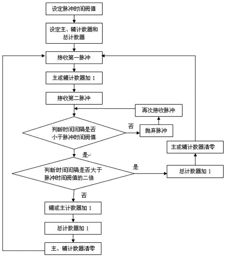
[0024] attached figure 1 It is a schematic diagram of the steps of the reed switch pulse type gas meter metering method of the present invention, as can be seen from the figure, the reed switch pulse type gas meter metering method of the present invention, the controller MCU sets the pulse time threshold value according to the interval time of the pulse received, Set up the main and auxiliary counters and the total counter, wherein the main and auxiliary counters correspond to two reed switches respectively; when the first pulse is received, the main or auxiliary counter is incremented by 1 and starts counting; when the second pulse is received , to determine whether the interval between it and the first pulse is less than the pulse time threshold; if so, discard it and receive a new pulse, otherwise, determine whether the interval between it and the first pulse is greater than the pulse time threshold double; if yes, add 1 to the total counter, and at the same time, clear the...


PUM


Abstract

The present invention proposes a reed switch pulse type gas meter metering method. The controller MCU sets the pulse time threshold according to the interval time of the received pulses, and sets up the main and auxiliary counters and the total counter. When the first pulse is received , the main or auxiliary counter adds 1 and starts counting; when the second pulse is received, judge whether the interval between it and the first pulse is less than the pulse time threshold; if so, discard it and receive a new pulse , otherwise, judge whether the interval time between it and the first pulse is greater than twice the pulse time threshold; if yes, add 1 to the total counter, and at the same time, clear the main or auxiliary counter to receive a new pulse; otherwise, then Increment the auxiliary or main counter by 1, and at the same time, increase the total counter. The beneficial technical effect of the present invention is that it can effectively remove jitter pulses, avoid "overmetering" of flow rate, and at the same time, avoid "missing metering" of flow rate, thereby effectively improving the accuracy of metering.

Description

technical field [0001] The invention relates to the metering technology of a reed switch pulse type gas meter, in particular to a metering method of a reed switch pulse type gas meter. Background technique [0002] The reed switch pulse gas meter uses a permanent magnet to trigger the closing or opening of the reed switch to generate pulses, and calculates the pulse data to calculate the gas flow. Specifically, a permanent magnet is embedded between the last character wheels of the meter, and dry reed switches are symmetrically arranged on both sides of the last character wheel. When gas flows through the pipeline and drives the rotating system to rotate, the rotating system will Drive the last character wheel to rotate, and the permanent magnet set on the last character wheel also rotates accordingly. When the permanent magnet passes through the dry reed tubes symmetrically arranged on both sides of the last character wheel, the reed tube reeds are attracted; the permanent ...

Claims


Application Information

Patent Timeline
Patent Type & Authority Patents(China)
IPC IPC(8): G01F15/075
Inventor 李克勤熊涛龙宪韩徐义洲李良姚婵娟谭巍刘英杰
Owner CHONGQING SHANCHENG GAS EQUIP
Learn More