Built-up hole punching device

A technology for punching and forming holes, which is applied in the field of multi-stage forming molds, and can solve problems such as the inability to use punching machines

Inactive Publication Date: 2015-04-08
CHONGQING YUANCHUANG AUTOMATION EQUIP
View PDF0 Cites 5 Cited by
  • Summary
  • Abstract
  • Description
  • Claims
  • Application Information

AI Technical Summary

Problems solved by technology

[0003] The conventional stamping process is that the punch is punched from top to bottom. However, such stamping will cause the burr of the flanging pre-punching hole to be located in the same direction as the flanging punch. For the direction control of the specific burr, the pre-punching hole If the burr is located in the reverse position of the punch, the conventional punching machine cannot be used

Method used


Image

  • Built-up hole punching device

Examples


Embodiment Construction

[0018] The present invention will be described in further detail below by means of specific embodiments:

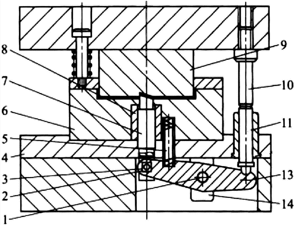
[0019] The reference signs in the drawings of the specification include: fulcrum 1, pin hole 2, pin shaft 3, cushion body 4, compression spring 5, lower die 6, punch 7, hollow sleeve body 8, upper die 9, hydraulic rod 10, Guide sleeve 11, adjusting rod 13, pole 14.

[0020] Such as figure 1 As shown, the hole forming punch of the present invention includes an upper die 9 and a lower die 6, wherein the upper die 9 is a convex die, the lower die 6 is a groove, the lower die 6 is installed on the lower die 6 frame, and the upper die 9 is installed on On the upper mold 9 racks.

[0021] Upper die 9 is moved down driven by a hydraulic cylinder, and upper die 9 is provided with a through hole leading into lower die 6, and the through hole is provided with a hydraulic rod 10 driven by a hydraulic cylinder.

[0022] The hydraulic rod 10 is connected with the adjustment lever a...


PUM


Abstract

The invention relates to a multistage workstation forming die, in particular to a built-up hole punching device which comprises an upper die, a lower die, a hydraulic rod, an adjusting lever and a punch. The upper die is a convex die, the lower die is a concave die and is mounted on a lower die frame, the upper die is mounted on an upper die frame, the hydraulic rod, the adjusting lever and the punch are connected sequentially, the hydraulic rod is connected with a power arm of the adjusting lever, the punch is connected with a resistance arm of the adjusting lever, a groove is matched with a preset built-up hole in shape is formed in the convex die, a through hole for the hydraulic rod to penetrate out is formed in the upper die, the adjusting lever is arranged on the lower die frame, the punch penetrates the lower die and goes into the groove, and the top end of the punch and the groove are matched in shape. The defect that burrs are positioned in the direction of the convex die in the prior art is overcome, and the built-up hole punching device enables burrs of a pre-punched hole to be positioned in the direction of the convex die.

Description

technical field [0001] The invention relates to a multi-stage station forming die, in particular to a hole-forming punch. Background technique [0002] With the continuous improvement of the mold manufacturing process, at present, various manufacturers have generally integrated the punching and forming steps in the production of parts into a pair of molds to reduce costs, and set the punch for opening the hole on the forming punch. The part to be processed is placed in front of the forming die, the forming punch moves to the part and the punch is used to complete the opening of the part, and then the forming punch continues to move until the two sides of the part are respectively attached to the mold surfaces of the forming punch and the forming die. Combined to complete the molding of the part. [0003] The conventional stamping process is that the punch is punched from top to bottom. However, such stamping will cause the burr of the flanging pre-punching hole to be locate...

Claims


Application Information

Patent Timeline
Patent Type & Authority Applications(China)
IPC IPC(8): B21D37/10B21D37/12B21D35/00
CPCB21D37/10B21D35/003B21D37/12
Inventor 陈振丰
Owner CHONGQING YUANCHUANG AUTOMATION EQUIP
Why Eureka
Try Eureka