Steel bar cutting machine
A steel bar cutting machine and rotating motor technology, applied in the field of cutting machines, can solve the problems of loose locking, clogged cutting head, cutting position deviation, etc., and achieve the effect of simple and reasonable structure, accurate and fast cutting
- Summary
- Abstract
- Description
- Claims
- Application Information
AI Technical Summary
Problems solved by technology
Method used
Image

Examples
Embodiment Construction
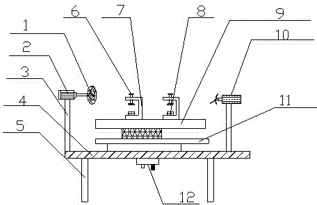
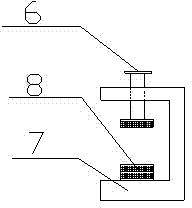
[0011] Such as figure 1 Shown, a kind of steel bar cutting machine, it comprises cutting device, workbench 4 and the slide rail 9 that is arranged on workbench 4, guide rail 11, and described cutting device is arranged on described workbench 4 by support bar 3 The rotary motor 2 and the grinding wheel 1 connected to the output end of the rotary motor 2 are composed; the slide rail 9 realizes the sliding displacement through the slider provided on the bottom surface of the slide rail 9 and the guide rail 11, and the mutual cooperation between the slide rail, the slide block and the guide rail , the sliding movement of the steel bar to be cut is realized, which is convenient for cutting in the next step; an electric fan 10 is arranged on the other side of the workbench 4 relative to the rotating motor 2, and the electric fan 10 is set by a support rod 3 On the workbench 4, the electric fan provided can not only blow off the residue generated when cutting the steel bar, but also ...
PUM
 Abstract
Description
Claims
Application Information
PatSnap Eureka turns technology decisions into work you can execute. Powered by our Innovation Knowledge Graph, it runs expert workflows across engineering, life sciences, materials and intellectual property. Get your review-ready output in minutes.


